
Driver circuit, corresponding device and method of operation

Active Publication Date: 2022-01-06
STMICROELECTRONICS SRL
View PDF0 Cites 2 Cited by
  • Summary
  • Abstract
  • Description
  • Claims
  • Application Information

AI Technical Summary

Benefits of technology

The purpose of the patent is to improve the efficiency and durability of driver circuits used in half-bridge switching circuits.

Problems solved by technology

Known circuit arrangements for driving GaN power transistors in half-bridge switching circuits may not provide satisfactory performance in terms of efficiency and / or robustness.

Method used


Image

  • Driver circuit, corresponding device and method of operation
  • Driver circuit, corresponding device and method of operation
  • Driver circuit, corresponding device and method of operation

Examples


Embodiment Construction

[0022]In the ensuing description, one or more specific details are illustrated, aimed at providing an in-depth understanding of examples of embodiments of this description. The embodiments may be obtained without one or more of the specific details, or with other methods, components, materials, etc. In other cases, known structures, materials, or operations are not illustrated or described in detail so that certain aspects of embodiments will not be obscured.

[0023]Reference to “an embodiment” or “one embodiment” in the framework of the present description is intended to indicate that a particular configuration, structure, or characteristic described in relation to the embodiment is comprised in at least one embodiment. Hence, phrases such as “in an embodiment” or “in one embodiment” that may be present in one or more points of the present description do not necessarily refer to one and the same embodiment. Moreover, particular conformations, structures, or characteristics may be com...


PUM


Abstract

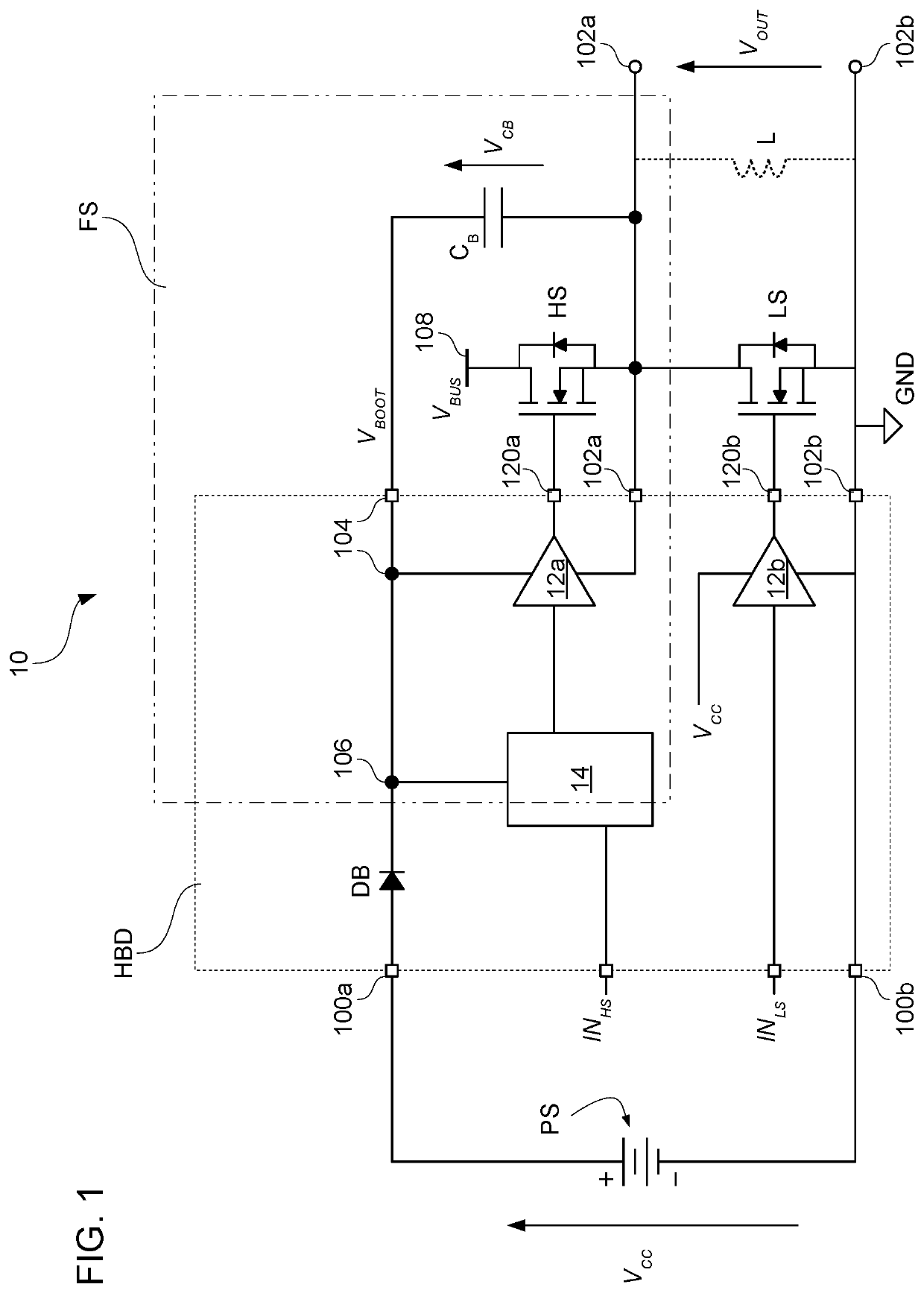
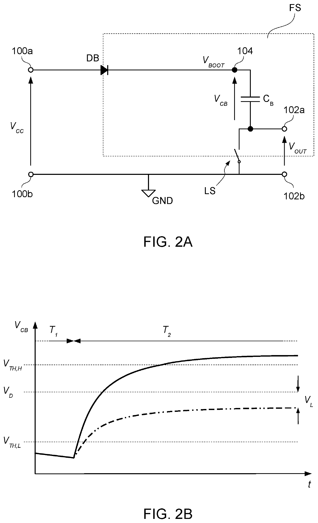
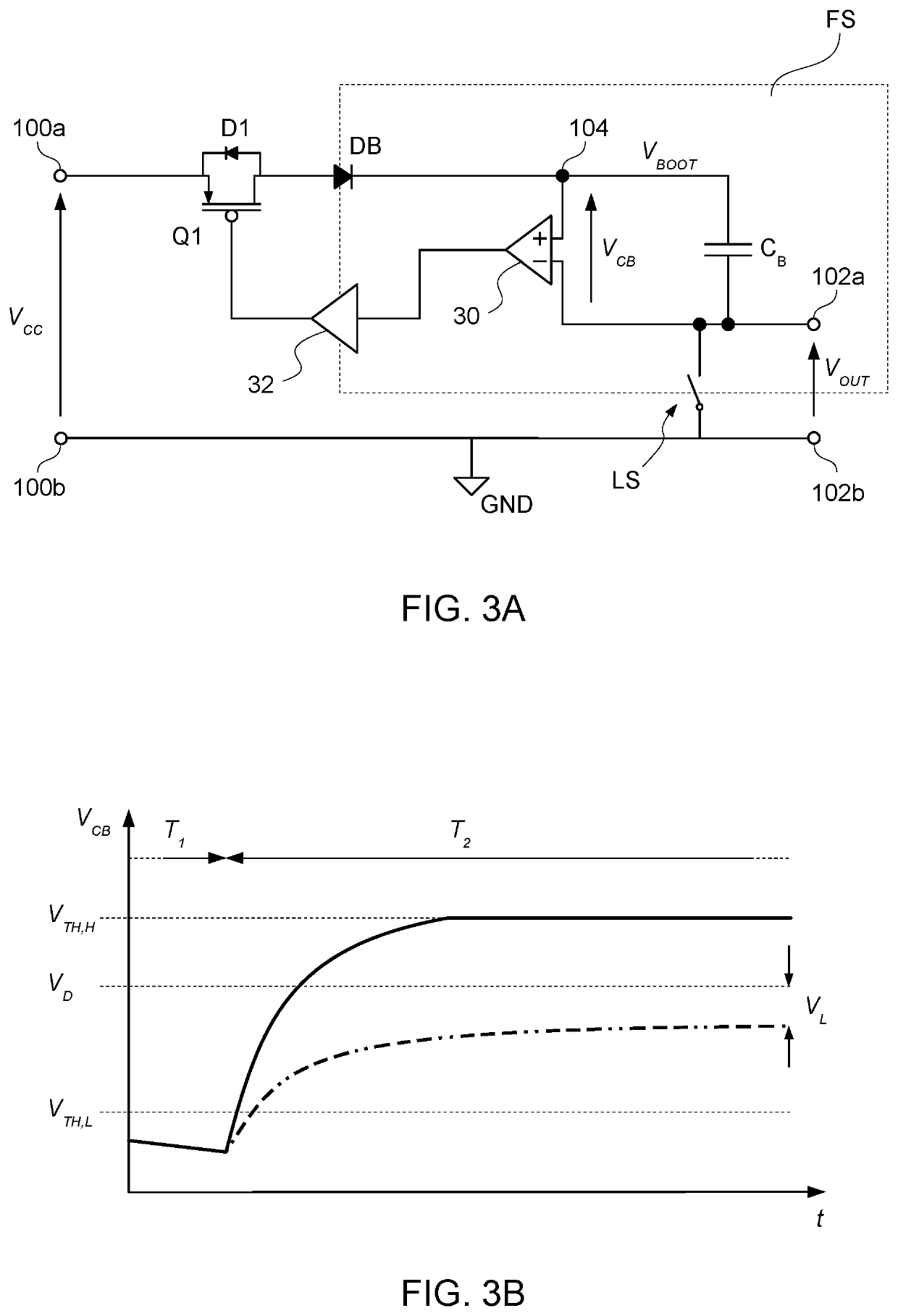
A circuit comprises first and second input supply nodes configured to receive a supply voltage therebetween. The circuit comprises a high-side driver circuit configured to be coupled to a high-side switch and produce a first signal between first and second high-side output nodes. The circuit comprises a low-side driver circuit configured to be coupled to a low-side switch and produce a second signal between first and second low-side output nodes. The circuit comprises a floating node configured to receive a floating voltage applied between the floating node and the second high-side output node, a bootstrap diode between the first input supply node and an intermediate node, and a current limiter circuit between the intermediate node and the floating node and configured to sense the floating voltage and counter a current flow from the intermediate node to the floating node as a result of the floating voltage reaching a threshold value.

Description

BACKGROUNDTechnical Field[0001]The description relates to half-bridge switching circuits with high-side bootstrap architecture.Description of the Related Art[0002]High voltage (HV) half-bridge switching circuits as known in the art may be used in various applications such as motor driver devices, electronic ballasts for fluorescent lamps, power supply devices and other devices.[0003]Gallium nitride (GaN) power transistors are increasingly used in half-bridge switching circuits in the place of conventional power transistors (such as conventional silicon MOS field-effect transistors or insulated-gate bipolar transistors, IGBT) with the aim of improving the overall efficiency of the switching circuits. For instance, GaN power transistors may provide lower gate capacitance and higher switching speed.[0004]Known circuit arrangements for driving GaN power transistors in half-bridge switching circuits may not provide satisfactory performance in terms of efficiency and / or robustness.BRIEF S...

Claims


Application Information

Patent Timeline
IPC IPC(8): H03K17/06H03K17/0812
CPCH03K17/063H03K17/08122H03K2217/0072H03K2217/0063H03K2217/0081H02M1/08H02M1/0006H02M1/32
Inventor FONTANA, MARCO GIOVANNIRIVA, MARCOPULVIRENTI, FRANCESCOCANTONE, GIUSEPPE
Owner STMICROELECTRONICS SRL
Learn More