Double-flow turbojet engine assembly with epicycloidal or planetary gearbox

Active Publication Date: 2022-01-13
SN DETUDE & DE CONSTR DE MOTEURS DAVIATION S N E C M A
View PDF0 Cites 0 Cited by
  • Summary
  • Abstract
  • Description
  • Claims
  • Application Information

AI Technical Summary

Benefits of technology

The patent is about an invention that reduces the speed of the main shaft and increases the length of the shaft to reduce the frequency of vibrations. This reduces the risk of damage to the fan blades and allows for a larger fan size without causing excessive tip speeds.

Problems solved by technology

In practice, the low-pressure spool is a critical element of the assembly, because its central shaft extends substantially over the entire length of the engine, so that during operation, that is to say when it rotates, it may be subject to vibration modes that could lead to the destruction of the engine.
Such bearings, generally referred to by the acronym SFD meaning “squeeze film dampers” include a fixed soft cage carrying a bearing receiving the central shaft, and around which a hydraulic pressure is maintained, this bearing type being expensive to implement.

Method used


Image

  • Double-flow turbojet engine assembly with epicycloidal or planetary gearbox
  • Double-flow turbojet engine assembly with epicycloidal or planetary gearbox
  • Double-flow turbojet engine assembly with epicycloidal or planetary gearbox

Examples


Embodiment Construction

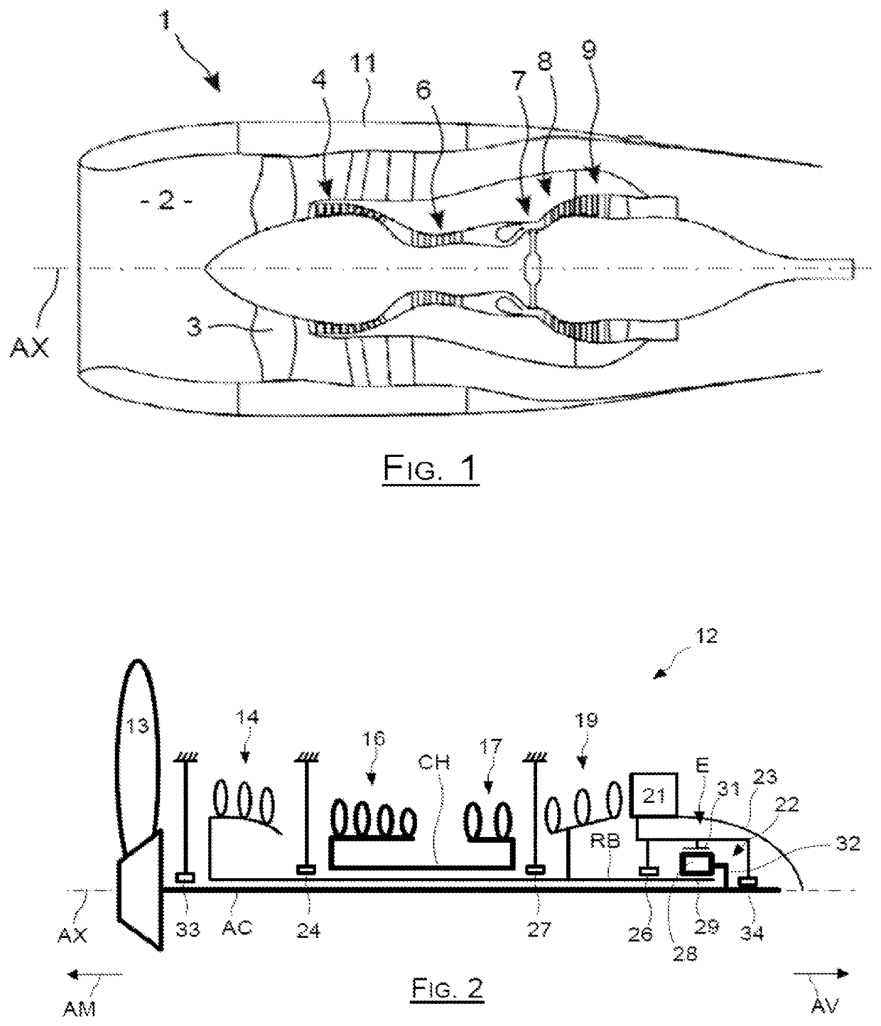
[0044]As schematically represented in FIG. 2, the engine according to the invention features an architecture comprising a fan 13 at its upstream portion AM which is driven in rotation by a central shaft AC extending over most of the length of the engine, from upstream AM to downstream AV defined with respect to the direction of circulation of the flow in this engine, in accordance with usual conventions.

[0045]This fan 13 is followed by a low-pressure compressor 14 which belongs to a low-pressure rotor RB surrounding the central shaft AC, this low-pressure compressor 14 being followed by a high-pressure compressor 16, to compress the flow before it is drawn into a non-represented combustion chamber located immediately downstream of this high-pressure compressor 16.

[0046]After passage in the combustion chamber, the fluid expands through a high-pressure turbine 17 which drives the compressor 16. The blades of the high-pressure compressor 16 and of the high-pressure turbine 17 are carri...


PUM


Abstract

A turbojet engine including a shaft surrounded by a low-pressure rotor surrounded by a coaxial and independent high-pressure spool, this turbojet engine including from upstream to downstream: a fan driven by the shaft; a low-pressure compressor carried by the rotor; an inter-compressor casing; a high-pressure compressor and a high-pressure turbine carried by the high-pressure spool; an inter-turbine casing; a low-pressure turbine carried by the rotor; an exhaust casing; this turbojet engine including an upstream rotor bearing carried by the inter-compressor casing; a downstream rotor bearing carried by the exhaust casing; a gearbox downstream of the downstream bearing and through which the rotor drives the shaft; a downstream shaft bearing downstream of the downstream rotor bearing.

Description

TECHNICAL FIELD[0001]The invention relates to a twin-spool turbojet engine assembly integrating an epicycloidal or planetary gearbox.PRIOR ART[0002]In such an engine 1 represented in FIG. 1, air is drawn into an inlet duct 2 to pass through a fan 3 including a series of rotating blades before being split into a central primary flow and a secondary flow surrounding the primary flow.[0003]Afterwards, the primary flow is compressed in compression stages 4 and 6 before reaching a combustion chamber 7, after which it expands through a high-pressure turbine 8 and a low-pressure turbine 9 before being discharged rearwards. In turn, the secondary flow is propelled directly rearwards by the fan within a flow path delimited by the casing 11.[0004]Such a twin-spool type engine includes a so-called low-pressure spool by which the fan 3 is coupled to the low-pressure turbine, and a so-called high-pressure spool by which the compressor is coupled to the high-pressure turbine, these two spools bei...

Claims


Application Information

Patent Timeline
IPC IPC(8): F02C7/36F02C3/107F02K1/04F02C7/06
CPCF02C7/36F02C3/107F02K1/04F05D2220/36F05D2260/40311F05D2220/323F02C7/06F01D9/065F01D25/162F01D25/125Y02T50/60
Inventor BELMON, GUILLAUME CLAUDE ROBERTZACCARDI, CÉDRIC
Owner SN DETUDE & DE CONSTR DE MOTEURS DAVIATION S N E C M A
Why Eureka
Try Eureka