Shape memory deployable rigid antenna system
a rigid antenna and shape memory technology, applied in the direction of antennas, antenna details, electrical equipment, etc., can solve the problems of not teaching the deployment of shape memory solid reflectors or sub-reflector supports, assembly offers a very dense package, and none of the prior art above suggests or teaches deployable shape memory solid reflectors created from folded/corrugated preforms, etc., to achieve the effect of reducing the weight of instant antenna systems
- Summary
- Abstract
- Description
- Claims
- Application Information
AI Technical Summary
Benefits of technology
Problems solved by technology
Method used
Image
Examples
embodiment 4
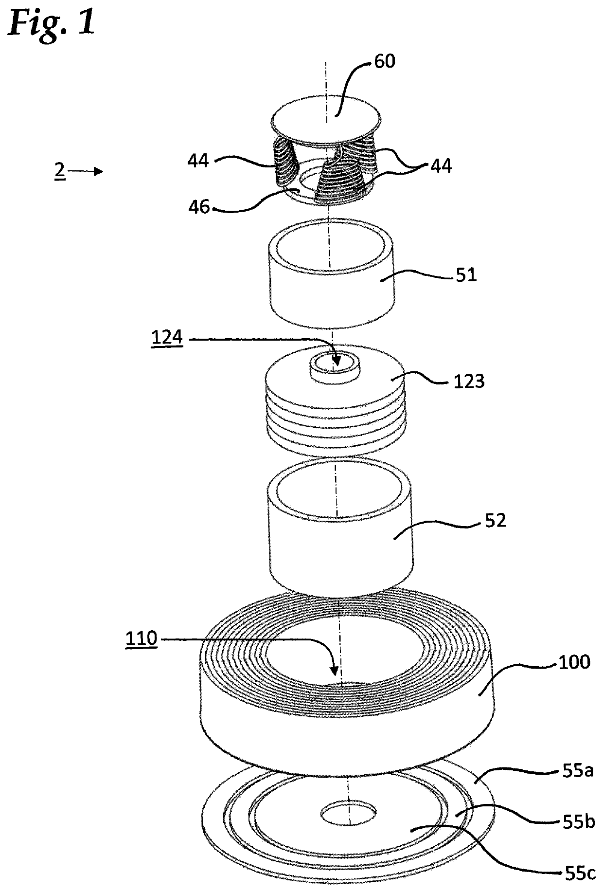
[0099]An alternative antenna system embodiment 4 is illustrated on FIGS. 11 and 12. It comprises dish 100 with an alternative feed assembly 40 nested inside it. Upon application of heat to its components antenna system 4 transitions to its deployed configuration 4a.
[0100]FIG. 13 depicts an alternative feed assembly 40 in stowed configuration. Feed 40 comprises secondary reflector 60 supported by extendable coiled supports 44 which rest on ring 46. Waveguide assembly 67 comprises nested tubular telescoping elements 62, 64, 66 and 68. Coiled feed actuator 48 is positioned around waveguide assembly and rests on ring 49. Numeral 43 denotes the lumen of waveguide assembly 67.
[0101]FIG. 14 depicts feed assembly 40 in its deployed configuration 40a. Secondary reflector supports 44 extend from their coiled stowed configuration to their deployed straightened configuration 44a upon being heated by heater 51 (not shown). Telescopic waveguide assembly 67 is extended into its deployed configura...
embodiment 6
[0105]An alternative antenna system embodiment 6 is illustrated on FIGS. 17 through 19. It comprises dish 100 and a feed assembly variant 150. Feed assembly 150 is similar in its construction to feed assembly 120, but secondary reflector 60 supports 156 are made integral with the feed body and are also made corrugated to extend longitudinally upon being heated. Supports 156 are separated by longitudinal slots 152 which permit electromagnetic energy emerging from feed lumen 124a to disperse upon reflection from reflector 60.
[0106]Upon application of heat supplied by heater 51 (not shown) supports 156 extend and assume their deployed shape 156a shown on FIG. 18. Also on FIG. 18, upon activation of heater 52 (not shown) feed body 123 extends and assumes its deployed configuration 123a, this configuration corresponding to the partially deployed antenna system configuration 6a. To complete deployment, dish 100 is transitioned into its deployed configuration 100a by cooperative action of ...
embodiment 8
[0107]An alternative antenna system embodiment 8 is shown on FIGS. 21 through 24.
[0108]Antenna system 8 is close in construction to embodiment 4, with the difference being the supports for secondary reflector 60 and an extendable feed assembly variant 47. Feed assembly 47 is almost identical to feed assembly 40 with the difference being the absence of supports 44. Its activation by heater 52 (not shown) through the action of coil 48 transitioning to its deployed configuration 48a, and its subsequent deployed configuration 47a are also similar to those of feed assembly 40.
[0109]Referring to FIG. 21, instead of supports extending from the waveguides of previous embodiments, reflector 60 is supported by coiled supports 160 connected to dish 100. Supports 160 extend from their stowed configuration to their extended configuration 160a upon application of heat by heater assembly 54 in the partial deployment of antenna system 8a depicted on FIG. 23. Heater assembly 54 is preferably of frus...
PUM
 Abstract
Description
Claims
Application Information
 - R&D
- Intellectual Property
- Life Sciences
- Materials
- Tech Scout
- Unparalleled Data Quality
- Higher Quality Content
- 60% Fewer Hallucinations
Browse by: Latest US Patents, China's latest patents, Technical Efficacy Thesaurus, Application Domain, Technology Topic, Popular Technical Reports.
© 2025 PatSnap. All rights reserved.Legal|Privacy policy|Modern Slavery Act Transparency Statement|Sitemap|About US| Contact US: help@patsnap.com


