
Mobility service delivery method, mobility service system, and management server

Pending Publication Date: 2022-01-20
TOYOTA JIDOSHA KK
View PDF0 Cites 0 Cited by
  • Summary
  • Abstract
  • Description
  • Claims
  • Application Information

AI Technical Summary

Benefits of technology

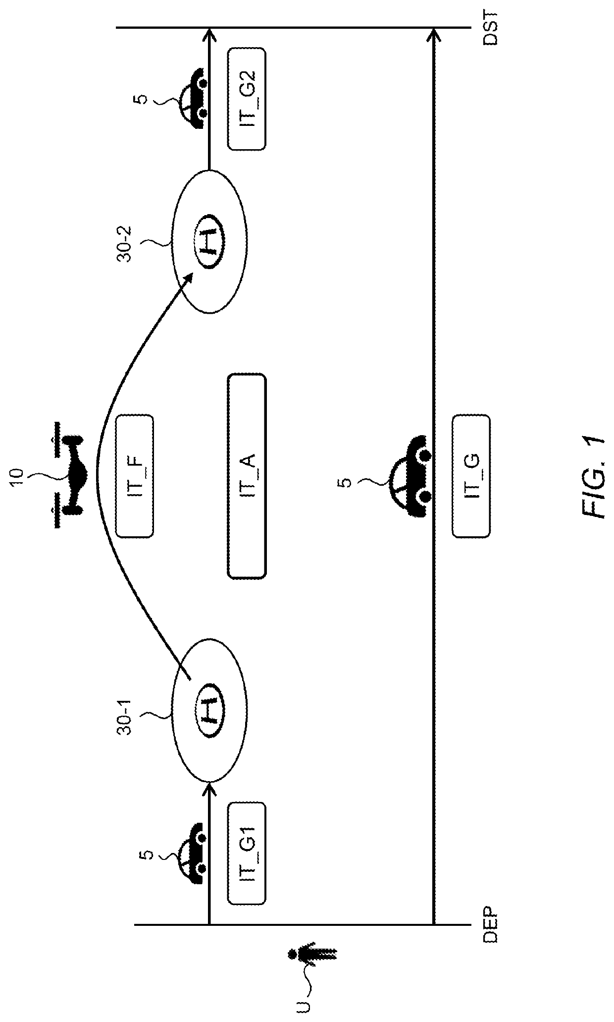
The present invention aims to provide a technique that can enhance opportunities for using the eVTOL for mobility services. It proposes a method of planning an itinerary even if the flight range of the first eVTOL is limited, which expands the available options for mobility service providers.

Problems solved by technology

However, there is naturally a limit on a distance for which the eVTOL is able to fly on a single charge, that is, a flight range of the eVTOL.
Therefore, when a flight with a distance longer than the flight range of the eVTOL is requested, it is difficult to accept a reservation.
This leads to decrease in service delivery opportunity.

Method used


Image

  • Mobility service delivery method, mobility service system, and management server
  • Mobility service delivery method, mobility service system, and management server
  • Mobility service delivery method, mobility service system, and management server

Examples


third example

3-2-3. Third Example

[0122]FIG. 17 is a flow chart showing a third example of the itinerary planning process (Step S200). The third example is a modification example of the second example shown in FIG. 16. As described above, when the use of the eVTOL 10 is specified (Step S210; Yes), the information processing device 130 plans both the itinerary IT-A and the itinerary IT-G (Steps S230 and S240). Furthermore, in Step S250, the information processing device 130 compares the required time TR-A of the itinerary IT-A and the required time TR-G of the itinerary IT-G. When the required time TR-A is equal to or less than the required time TR-G (Step S250; Yes), the information processing device 130 selects both the itinerary IT-A and the itinerary IT-G as candidates (Step S260). On the other hand, when the required time TR-A is longer than the required time TR-G (Step S250; No), the information processing device 130 discards the itinerary IT-A and selects the itinerary IT-G as a candidate (...

first example

5-1. First Example

[0146]FIG. 21 is a conceptual diagram for explaining a first example. In the first example, the flight range of the first eVTOL 10-1 is less than the flight distance D12 from the first takeoff and landing site 30-1 to the second takeoff and landing site 30-2. However, the first eVTOL 10-1 is a “specific eVTOL 10-S.” The specific eVTOL 10-S is an eVTOL 10 whose battery is replaceable, or an eVTOL 10 that is rechargeable within a predetermined (e.g., 8 minutes).

[0147]A third takeoff and landing site 30-3 is located between the first takeoff and landing site 30-1 and the second takeoff and landing site 30-2. Moreover, the third takeoff and landing site 30-3 is located within the flight range of the first eVTOL 10-1 from each of the first takeoff and landing site 30-1 and the second takeoff and landing site 30-2. That is, the flight range of the first eVTOL 10-1 is equal to or greater than a flight distance D13 from the first takeoff and landing site 30-1 to the third ...

second example

5-2. Second Example

[0151]FIG. 22 is a conceptual diagram for explaining a second example. In the second example as well, the flight range of the first eVTOL 10-1 is less than the flight distance D12 from the first takeoff and landing site 30-1 to the second takeoff and landing site 30-2. In addition, the first eVTOL 10-1 is not the specific eVTOL 10-S.

[0152]A fourth takeoff and landing site 30-4 is located between the first takeoff and landing site 30-1 and the second takeoff and landing site 30-2. Moreover, the fourth takeoff and landing site 30-4 is located within the flight range of the first eVTOL 10-1 from the first takeoff and landing site 30-1. That is, the flight range of the first eVTOL 10-1 is equal to or greater than a flight distance D14 from the first takeoff and landing site 30-1 to the fourth takeoff and landing site 30-4. Furthermore, a second eVTOL 10-2 different from the first eVTOL 10-1 is available at the fourth takeoff and landing site 30-4 at the reservation da...


PUM


Abstract

An itinerary including a flight from a first takeoff and landing site to a second takeoff and landing site is planned. If a flight range of a first eVTOL available is less than a flight distance from the first takeoff and landing site to the second takeoff and landing site, and if the first eVTOL is a battery-replaceable eVTOL or an eVTOL rechargeable within a predetermined time, a third takeoff and landing site located within the flight range from each of the first and second takeoff and landing sites and having a battery replacement facility or a battery charging facility is searched for. The planned itinerary includes a flight from the first takeoff and landing site to the third takeoff and landing site by the first eVTOL and another flight from the third takeoff and landing site to the second takeoff and landing site by the first eVTOL.

Description

CROSS-REFERENCE TO RELATED APPLICATION[0001]The present application claims priority under 35 U.S.C. § 119 to Japanese Patent Application No. 2020-122885, filed Jul. 17, 2020, the contents of which application are incorporated herein by reference in their entirety.BACKGROUNDTechnical Field[0002]The present disclosure relates to a technique of delivering a mobility service utilizing an electric vertical takeoff and landing aircraft (eVTOL).Background Art[0003]Japanese Laid-Open Patent Application Publication No. JP-2019-214370 discloses an electric multi-rotor aircraft. For example, the electric multi-rotor aircraft is an electric vertical takeoff and landing aircraft.SUMMARY[0004]In recent years, a concept of MaaS (Mobility as a Service) has been proposed, and a mobility service utilizing a variety of mobility modes (transportation) in an integrated manner has been proposed. It is conceivable to utilize, as the mobility mode, not only a ground mobility mode such as an automobile and ...

Claims


Application Information

Patent Timeline
IPC IPC(8): G05D1/10B64C13/18B64D27/24G01C23/00
CPCG05D1/102B64C13/18G01C23/00B64D27/24G05D1/104G06Q10/02G06Q10/109G06F16/9532G06F16/9537G06F16/9538G06Q50/40G05D1/00G01C21/20
Inventor OTA, SHUNOTAKI, YOSHIFUMI
Owner TOYOTA JIDOSHA KK
Learn More