Control method for internal combustion engine

Inactive Publication Date: 2016-04-28
TOYOTA JIDOSHA KK
View PDF4 Cites 6 Cited by
  • Summary
  • Abstract
  • Description
  • Claims
  • Application Information

AI Technical Summary

Benefits of technology

The patent text describes a method for reducing the amount of nitrogen oxides (NOx) emitted from an internal combustion engine. By stopping the fuel supply to certain cylinders in the engine, air is allowed to be released from these cylinders, which helps to oxidize particulate matter collected in the engine's filter. This process, known as filter regeneration, can be performed without burning any fuel, resulting in a reduction in NOx emissions. The method also allows for more opportunities to perform filter regeneration while still reducing NOx emissions.

Problems solved by technology

Hence, in a gasoline engine that is operated at the stoichiometric air-fuel ratio or a rich air-fuel ratio, it is difficult to regenerate the filter simply by increasing the engine rotation speed, even when the temperature of the filter equals or exceeds the predetermined temperature.
Moreover, at a lean air-fuel ratio, it is difficult to purify the NOx using a three-way catalyst provided on an upstream side of the filter, for example.

Method used


Image

  • Control method for internal combustion engine
  • Control method for internal combustion engine
  • Control method for internal combustion engine

Examples


first embodiment

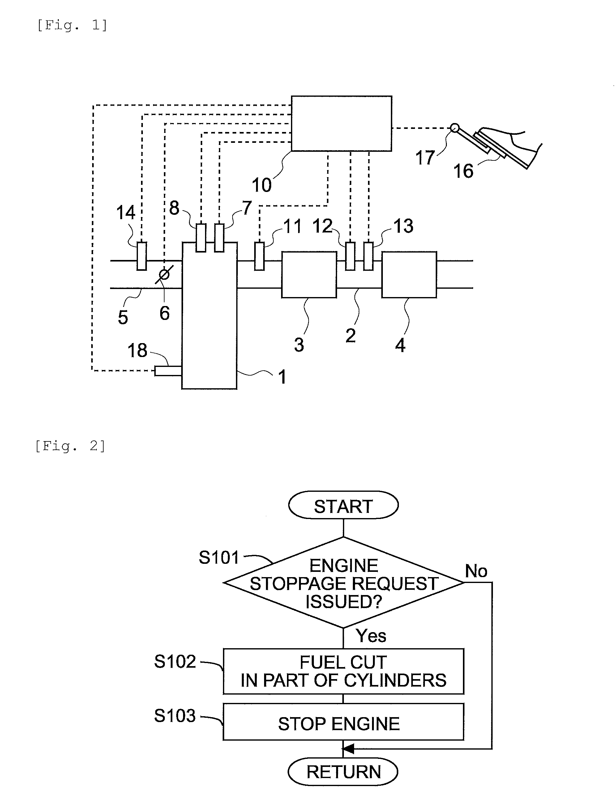
[0069]FIG. 1 is a schematic view showing a configuration of an internal combustion engine according to an embodiment, together with an intake system and an exhaust system thereof. An internal combustion engine 1 shown in FIG. 1 is a spark ignition type gasoline engine. The internal combustion engine 1 is installed in a vehicle, for example. Further, the internal combustion engine 1 includes a plurality of cylinders.

[0070]An exhaust passage 2 is connected to the internal combustion engine 1. A catalyst 3 and a filter 4 that collects PM contained in exhaust gas are provided midway in the exhaust passage 2 in that order from an upstream side.

[0071]The catalyst 3 purifies the exhaust gas. The catalyst 3 may be a three-way catalyst, an oxidation catalyst, a NOx storage reduction catalyst, or a NOx selective reduction catalyst, for example. Note that in this embodiment, the catalyst 3 is not essential.

[0072]Further, a first temperature sensor 11 that detects a temperature of the exhaust g...

second embodiment

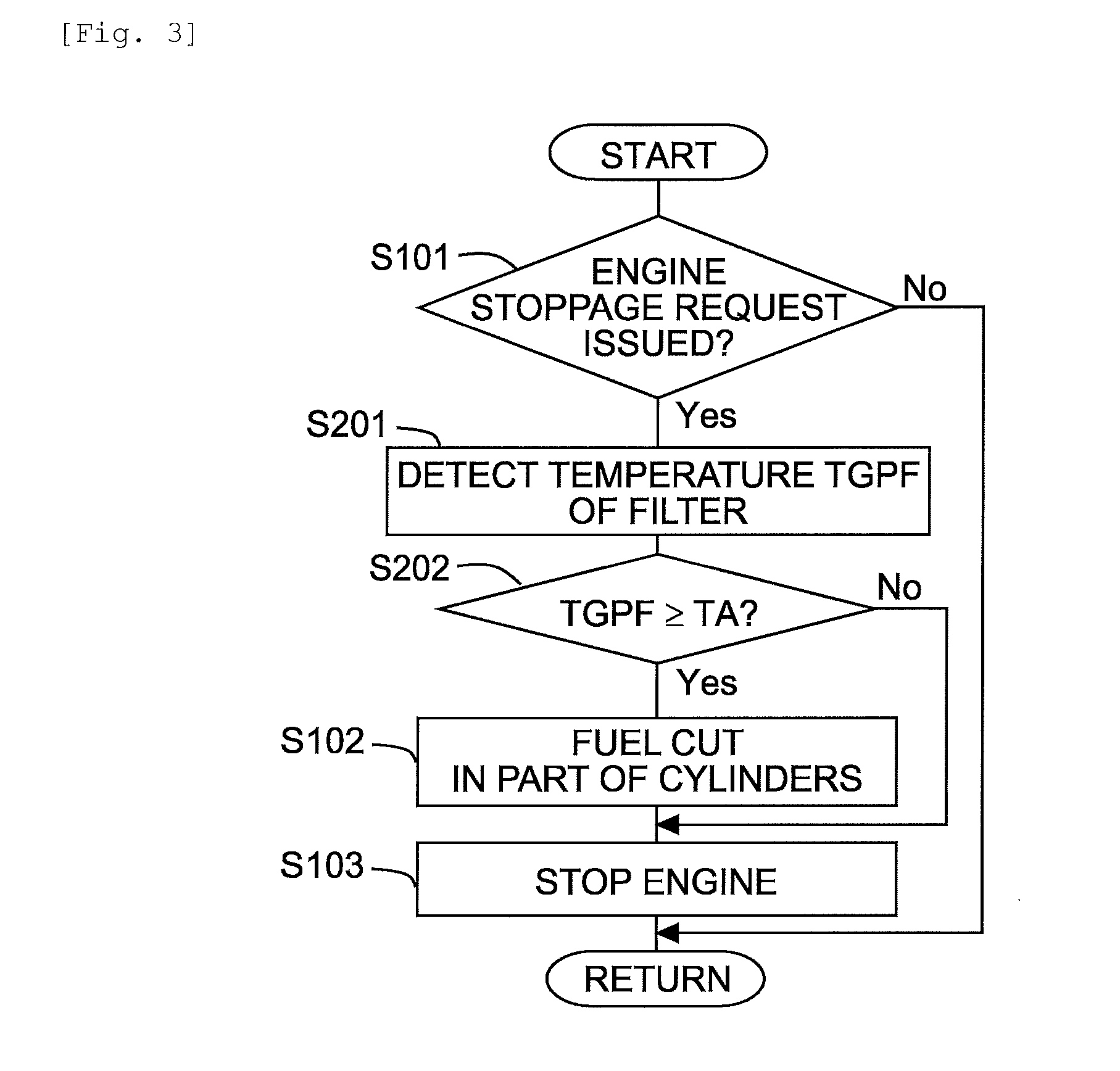
[0089]This embodiment differs from the first embodiment in the condition on which the fuel cut is implemented in the part of the cylinders before stopping the engine. All other apparatuses and so on are identical to the first embodiment, and therefore description thereof has been omitted.

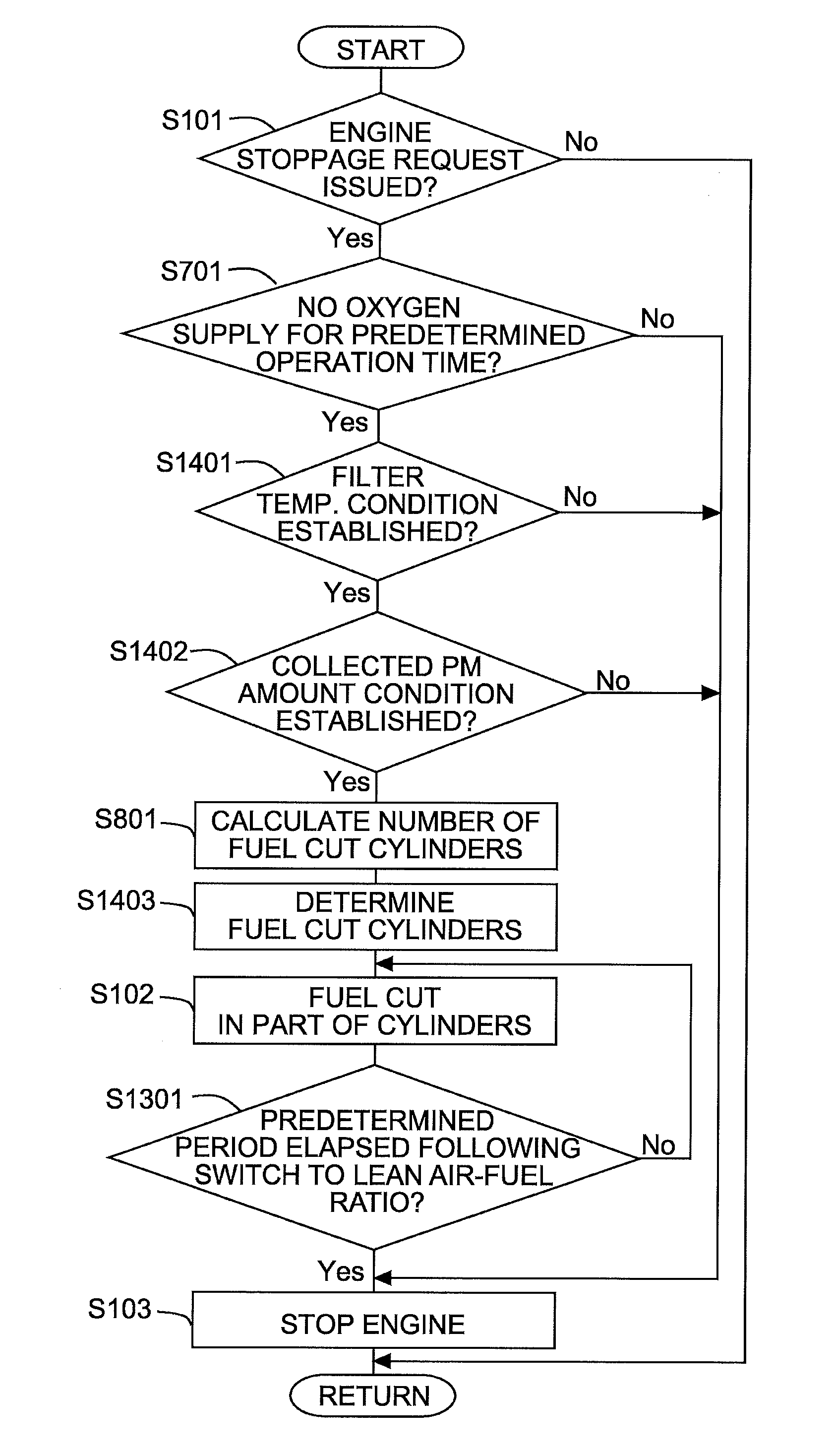
[0090]Here, to oxidize the PM, the temperature of the filter 4 must be sufficiently high. In other words, even when oxygen is supplied to the filter 4, the filter 4 cannot easily be regenerated until the temperature of the filter 4 reaches a temperature at which the PM can be oxidized. In this embodiment, therefore, the fuel cut is implemented in the part of the cylinders only when the temperature of the filter 4 equals or exceeds a predetermined lower limit temperature.

[0091]The predetermined lower limit temperature is a lower limit value of the temperature at which PM is oxidized. Further, the predetermined lower limit temperature may be set at a value having a certain amount of leeway relative to...

third embodiment

[0097]This embodiment differs from the above embodiments in the condition on which the fuel cut is implemented in the part of the cylinders before stopping the engine. All other apparatuses and so on are identical to the first embodiment, and therefore description thereof has been omitted.

[0098]Here, when oxygen is supplied to the filter 4 while the temperature of the filter 4 is high, the filter 4 may overheat due to reaction heat generated during oxidation of the PM in the filter 4. When the filter 4 overheats, the filter 4 may break, for example, and in a case where a catalyst is carried on the filter 4, the catalyst may deteriorate.

[0099]In this embodiment, therefore, the fuel cut is implemented in the part of the cylinders only when the temperature of the filter 4 is equal to or lower than a predetermined upper limit temperature. Here, the predetermined upper limit temperature is a larger value than the predetermined lower limit temperature according to the second embodiment. F...


PUM


Abstract

A control method for an internal combustion engine having a plurality of cylinders and a filter provided in an exhaust passage of the internal combustion engine in order to collect particulate matter. The control method includes a partial cylinder stoppage step, in which a supply of fuel is stopped in a part of a plurality of cylinders while continuing to supply fuel to the other cylinders such that combustion is performed therein, is implemented after a request to stop an internal combustion engine is issued but before the internal combustion engine is stopped, and after the partial cylinder stoppage step, an all cylinder stoppage step is implemented to stop the internal combustion engine by stopping the supply of fuel in all of the cylinders.

Description

TECHNICAL FIELD[0001]The present invention relates to a control method for an internal combustion engine.BACKGROUND ART[0002]A filter that collects particulate matter (referred to hereafter as PM) contained an exhaust gas may be provided in an exhaust passage of an internal combustion engine. When an amount of PM collected in the filter reaches a fixed amount, processing is implemented to oxidize, and thereby remove, the PM. This processing is known as filter regeneration.[0003]In a conventional technique employed in a diesel engine, when a vehicle is stopped while filter regeneration is underway and a temperature of the filter equals or exceeds a predetermined temperature, the filter is regenerated by increasing an engine rotation speed to a predetermined rotation speed. In another conventional technique, when a request to stop the internal combustion engine is issued while filter regeneration is underway, filter regeneration is continued by prohibiting stoppage of the engine until...

Claims


Application Information

Patent Timeline
IPC IPC(8): F02D41/02F01N3/20F01N3/021F02D41/30F02D41/00
CPCF02D41/0235F02D41/3005F01N3/20F01N3/021F02D41/0087F02D17/04F02D41/029F02D41/042F01N9/002F01N2430/02F01N2430/06F02D2200/0812Y02T10/40
Inventor TSUNOOKA, TAKASHIOTSUKA, TAKAYUKIKOBASHI, NORIYASU
Owner TOYOTA JIDOSHA KK
Why Eureka
Try Eureka