Eureka AIR delivers breakthrough ideas for toughest innovation challenges, trusted by R&D personnel around the world.

Medical instrument

Pending Publication Date: 2022-01-27
KARL STORZ GMBH & CO KG
View PDF7 Cites 0 Cited by
  • Summary
  • Abstract
  • Description
  • Claims
  • Application Information

AI Technical Summary

Benefits of technology

The invention proposes a guiding system for a tool that is easy and safe to use. The system includes axially displaceable elements for deflecting the tool tip and actuating the jaw parts. There is also a fourth element for releasing a jaw part latch. Additionally, the shaft is designed with a circular cross section for the first actuation element and semicircular cross sections for the other elements. This arrangement provides additional guiding and stabilization and saves space inside the instrument shaft. The technical effects are improved guiding, safety, and efficiency of the tool operation.

Problems solved by technology

However, on account of the actuation elements for deflecting the tool tip and for actuating the pivotable part being mounted eccentrically relative to the longitudinal axis of the instrument, it can happen that, when the jaw parts are subjected to considerable force, the two actuation elements sag and, in the bend region to the tool tip, protrude beyond the diameter of the instruments shaft, which can be problematic particularly when using a trocar.

Method used


Image

  • Medical instrument
  • Medical instrument
  • Medical instrument

Examples


Embodiment Construction

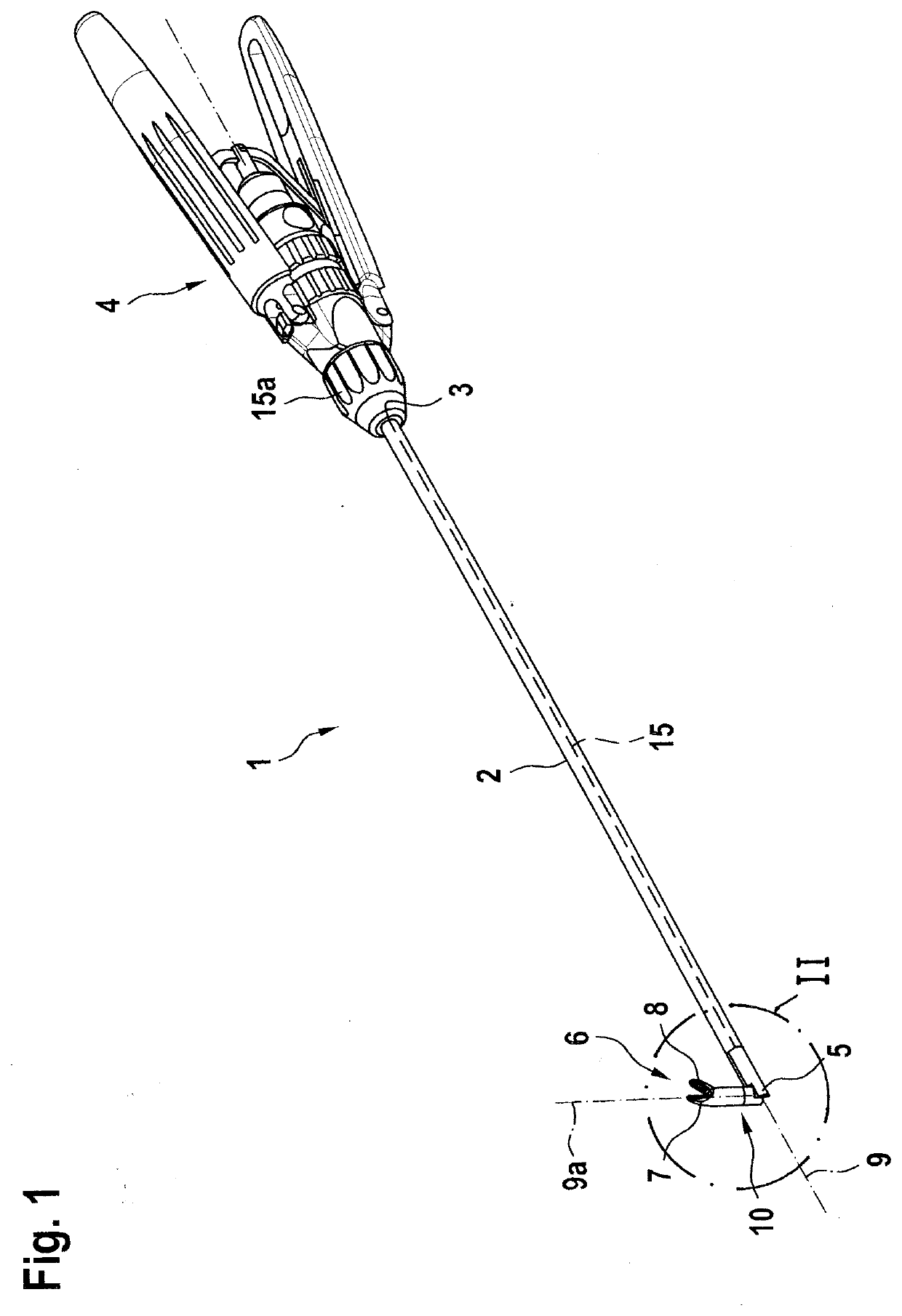
[0026]Referring to the drawings, FIG. 1 shows a medical instrument 1 with a hollow shaft 2, at the proximal end 3 of which a handle 4 is arranged, and at the distal end 5 of which a tool 6 is arranged which, in the illustrative embodiment shown, is composed of a stationary jaw part 7 and of a jaw part 8 pivotable with respect to the stationary jaw part 7.

[0027]According to an alternative embodiment, it is of course also possible for both jaw parts 7 and 8 to be configured to be pivotable relative to each other.

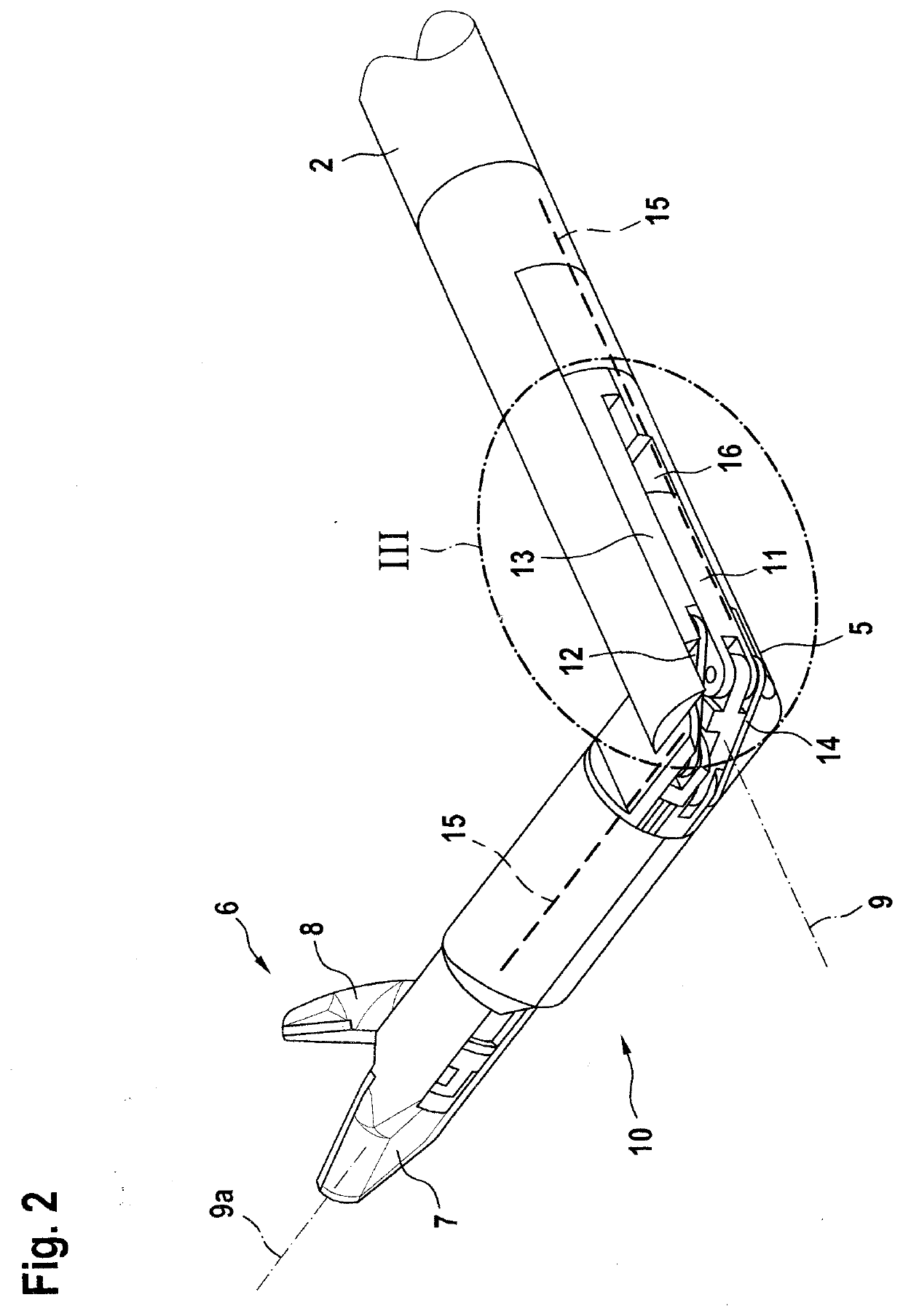
[0028]To give the tool 6 the greatest number of possible degrees of freedom of movement relative to the shaft 2, a distal end region of the shaft 2 that carries the tool 6 is configured as a tool tip 10 that can be deflected with respect to the longitudinal axis 9 of the shaft 2. In the view according to FIG. 1, the tool tip 10 is deflected by approximately 90° with respect to the longitudinal axis 9 of the shaft 2.

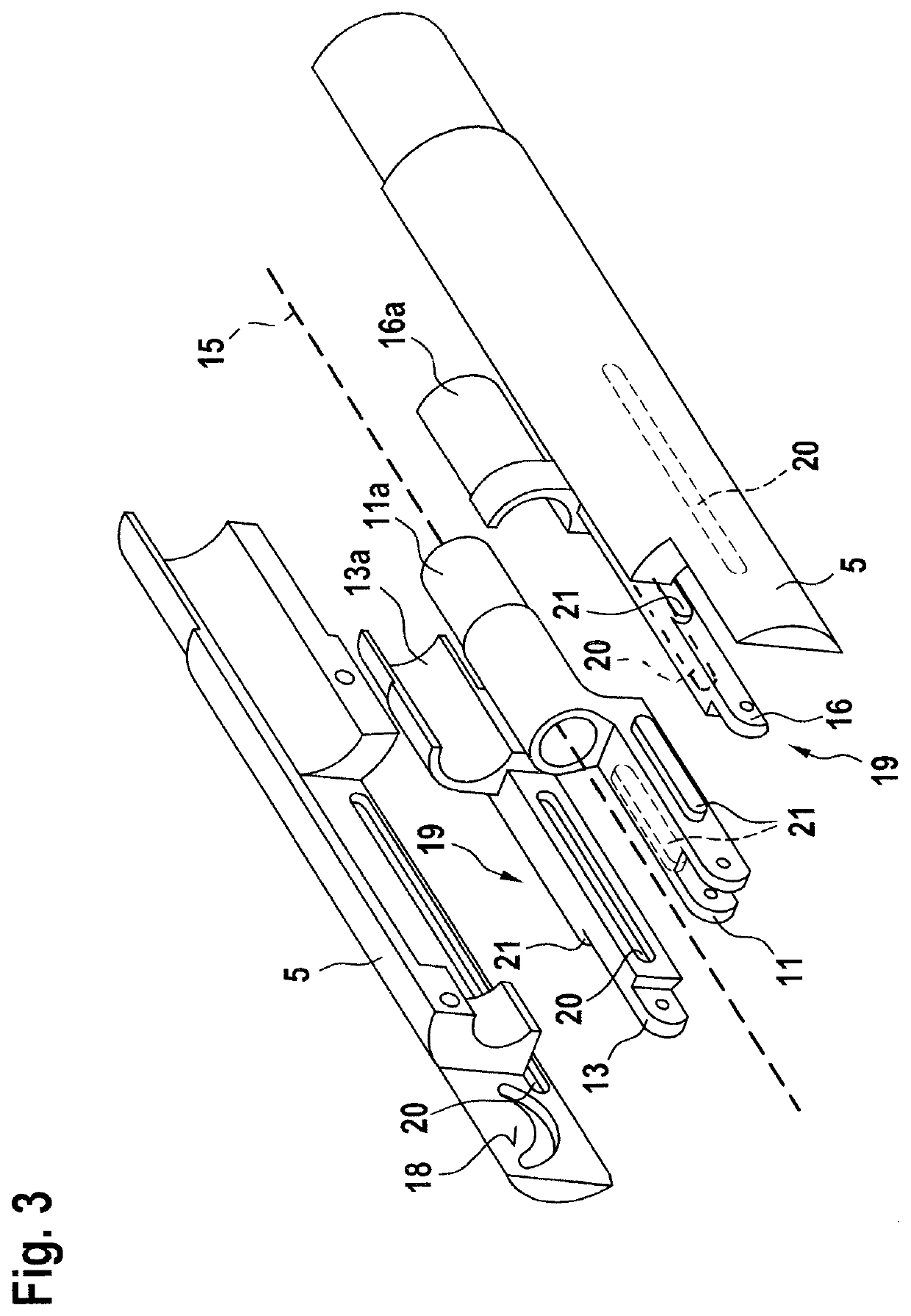
[0029]As can be seen from FIGS. 2 to 4, the deflection of the ...


PUM


Abstract

A medical instrument includes a hollow shaft (2) with a proximal end (3) connected to a handle (4) and a distal end (5) with a tool (6) arranged with one jaw part (8) pivotable relative to another jaw part (7). A distal end region of the shaft as a tool tip (10) deflects relative to a longitudinal axis (9) via an axially displaceable first actuation element (11) connected to the handle. The pivotable jaw part is adjustable via a second actuation element (13) mounted axially displaceably in the hollow shaft and connected to the handle. The first actuation element and the second actuation element are parallel to each other in the longitudinal axis direction of the shaft and mounted to be guided on each other. One of the two actuation elements is mounted on the inner side. The mutual axial mounting is effected via a pin-and-slot control (19).

Description

CROSS REFERENCE TO RELATED APPLICATIONS[0001]This application claims the benefit of priority under 35 U.S.C. § 119 of German Application 10 2020 119 462.5, filed Jul. 23, 2020, the entire contents of which are incorporated herein by reference.TECHNICAL FIELD[0002]The invention relates to a medical instrument with a hollow shaft, at the proximal end of which a handle is arranged, and at the distal end of which a tool is arranged with two jaw parts, wherein at least one jaw part is pivotable relative to the other jaw part, wherein a distal end region of the shaft that carries the tool is configured as a tool tip that can be deflected with respect to the longitudinal axis of the shaft, and wherein the deflection of the tool tip is effected via a first actuation element mounted axially displaceably in the hollow shaft and operatively connected at the proximal end to the handle, and wherein the at least one pivotable jaw part of the tool is adjustable between a closed and an opened posit...

Claims


Application Information

Patent Timeline
IPC IPC(8): A61B17/28
CPCA61B17/2841A61B17/282A61B17/2816A61B17/29A61B2017/2902A61B2017/2927A61B2017/2936
Inventor STEFAN, JOCHENKÄRCHER, DANIEL
Owner KARL STORZ GMBH & CO KG
Why Eureka
Eureka Blog
Learn More