Exhaust manifold

a manifold and exhaust technology, applied in the field of exhaust manifolds, can solve the problem of reducing the overall space requirements

Inactive Publication Date: 2009-06-04
DAIMLER AG
View PDF22 Cites 5 Cited by
  • Summary
  • Abstract
  • Description
  • Claims
  • Application Information

AI Technical Summary

Benefits of technology

[0018]The control element for influencing the exhaust gas recirculation rate is supported on an operating shaft, an operating means acting on the operating shaft in order to operate the control element. This affords an especially space-saving arrangement of the control element for influencing the exhaust gas recirculation rate in the central part.
[0019]Advantageously, a spring element, which is braced against an outer wall of the central part and which draws the operating shaft towards a support bearing, acts on the operating shaft. This makes it possible, in particular, to externally seal off the inside of the exhaust gas recirculation connection in the area of a shaft passage.

Problems solved by technology

This further reduces the overall space requirements.

Method used


Image

  • Exhaust manifold
  • Exhaust manifold
  • Exhaust manifold

Examples


Embodiment Construction

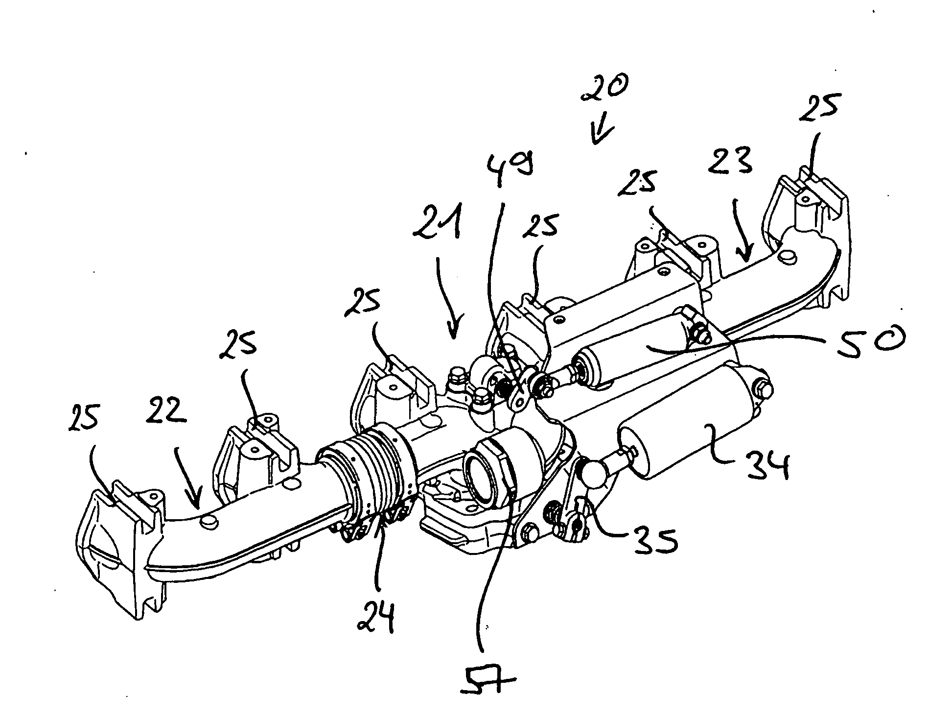
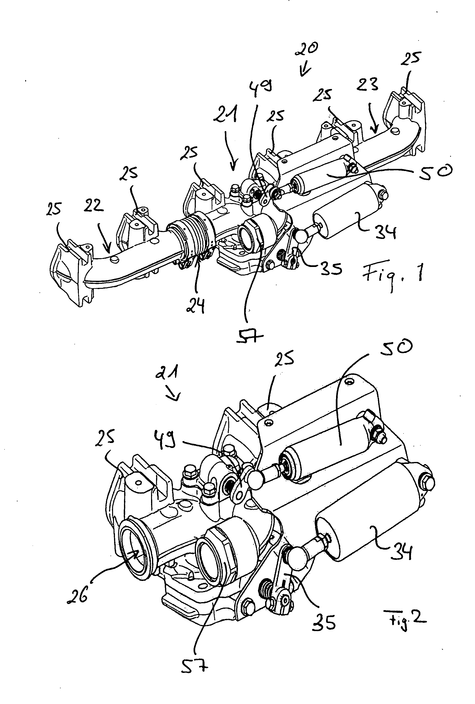
[0036]FIG. 1 shows a first exemplary embodiment of an exhaust manifold 20 according to the invention. The exhaust manifold 20 is intended for use in an internal combustion engine of a motor vehicle. FIGS. 2 to 7 show details of the exhaust manifold 20 in FIG. 1.

[0037]The exhaust manifold 20 in FIG. 1 comprises a central part 21 and two outer parts 22, 23, the two outer parts 22 and 23 being connected to the central part 21, each by way of a bellows-like intermediate piece 24.

[0038]The exhaust manifold 20 in FIG. 1 is designed for an internal combustion engine having six cylinders arranged in-line. The two outer parts 22, 23 and the central part 21 each comprise two connection branches 25 for attaching the exhaust manifold 20 to the internal combustion engine. Exhaust gas from the internal combustion engine can be discharged into the exhaust manifold 20 via the connection branches 25. The two connection branches 25 of the outer part 22 and a first connection branch 25 of the central ...


PUM


Abstract

In an exhaust manifold for an internal combustion engine including a central part with tow exhaust gas flow ducts extending from the central part in opposite directions for collecting exhaust gas from first and respectively second cylinder groups of the engine, the center part includes a first control valve for controlling the exhaust gas flow from the first and the second cylinder groups to first and second turbine inlet flow passages, a second control valve for controlling the exhaust gas pressure and a third control valve for controlling the exhaust gas recirculation rate.

Description

[0001]This is a Continuation-In-Part application of pending international patent application PCT / EP2007 / 005220 filed Jun. 13, 2007 and claiming the priority of German patent application 10 2006 030 748.8 filed Jun. 21, 2006.BACKGROUND OF THE INVENTION[0002]The invention relates to an exhaust manifold for an internal combustion engine comprising a central part that has two exhaust gas flow ducts, exhaust gas from a first cylinder group of the internal combustion engine being delivered to a first exhaust gas flow duct of the central part and exhaust gas from a second cylinder group of the internal combustion engine being delivered to a second exhaust gas flow duct of the central part, the first exhaust gas flow duct being connected to a first turbine flow passage and the second exhaust gas flow duct being connected to a second turbine flow passage.[0003]DE 103 57 925 A1 discloses an internal combustion engine having an exhaust gas system, which comprises a first exhaust gas flow duct ...

Claims


Application Information

Patent Timeline
Patent Type & Authority Applications(United States)
IPC IPC(8): F02D23/00F01N13/10
CPCF01N13/10F01N2260/14F01N2390/00F02D9/06F02B37/186F02M25/0748F02M25/0793Y02T10/121F02M25/0719F02M26/16F02M26/42F02M26/70
Inventor FRANTZHELD, GEROLFORLICH, JURGENRUESS, ANDREAS
Owner DAIMLER AG
Why Eureka
Try Eureka