Braking force generator for a hydraulic vehicle brake system

a technology of brake system and brake force, which is applied in the direction of brake system, mechanical equipment, transportation and packaging, etc., can solve the problems of affecting the braking performance, affecting the braking distance and the stability of the vehicle, and being regarded as a drawback, etc., to achieve convenient installation, economical cabling, and reliable operation

Inactive Publication Date: 2008-04-15
LUCAS AUTOMOTIVE GMBH
View PDF15 Cites 5 Cited by
  • Summary
  • Abstract
  • Description
  • Claims
  • Application Information

AI Technical Summary

Benefits of technology

[0009]The present invention generally provides a brake force generator of the initially described type that guarantees easily installable, economical cabling as well as reliable operation.
[0011]By virtue of the invention it is generally possible to keep the cabling outlay of the brake force generator low by providing the central connector, wherein the central connector has all of the contact elements needed for control of the brake force generator. Thus, when the brake force generator is assembled, for control thereof the central connector merely has to be connected to the vehicle electronics. The cabling outlay may therefore be kept relatively low. In particular, this avoids the need to contact a large number of different electric connectors at various points of the brake force generator.
[0016]To prevent the individual movements of various components of the brake force generator according to the invention from being impeded by the cabling, a development of the invention provides that the electric lines from the actuator to the central connector extend spirally or helically at least in one part of the chamber arrangement. The lines may therefore compensate movements of individual components.
[0021]With regard to the control device, a particularly space-saving arrangement and easy assembly is achieved when the control device is mechanically fitted directly on, and electrically connected to, the central connector and optionally the at least one auxiliary connector.
[0022]Furthermore, installation space may be saved also in that the central connector is formed integrally with the operating position detecting device. This may be achieved for example by integrating the central connector in the housing of the operating position detecting device. A further advantage of this form of construction according to the invention is that it allows a reduction of the number of parts to be assembled.
[0023]Assembly is further facilitated when the central connector is connected or connectable to a terminal connector for contacting electric lines to the actuating force generating device. In this connection, according to the invention it may also be provided that the terminal connector is constructed integrally with a receiving element, wherein the receiving element fastens the operating position detecting device to the base housing. It is therefore possible first to mount the receiving element on the base housing and then fit the operating position detecting device, which is constructed integrally with the central connector, on the receiving element. The control device may then be plugged onto the central connector and at the same time also optionally connected to the auxiliary connector. The result is a compact, space-saving and easy-to-assemble arrangement. Preferably, it is also provided that the central connector and optionally the auxiliary connector are fastened or fastenable to the base housing.

Problems solved by technology

With these brake systems, it has meanwhile begun to be regarded as a drawback that the driver by virtue of his actuating action at the brake pedal always influences the hydraulic pressure at the wheel brakes.
However, as soon as the driver reacts incorrectly to the actual braking situation, for example by adjusting too much or too little brake pressure, the braking performance, in particular the braking distance and the stability of the vehicle may be adversely affected, which in the worst-case scenario may lead to an accident.
Furthermore, it has meanwhile also begun to be regarded as unacceptable that the driver senses the action of the vehicle control system at the brake pedal, for example a repeated shaking at the brake pedal upon activation of the ABS.
It has however emerged that such brake systems are relatively cost-intensive to manufacture and entail a considerable equipment outlay in order to guarantee reliable brake operation also in the event of failure of the brake force generating means.
This leads to the drawbacks already outlined above, namely a high cabling outlay and a large number of plug-in connectors to be contacted.

Method used


Image

  • Braking force generator for a hydraulic vehicle brake system
  • Braking force generator for a hydraulic vehicle brake system
  • Braking force generator for a hydraulic vehicle brake system

Examples


Embodiment Construction

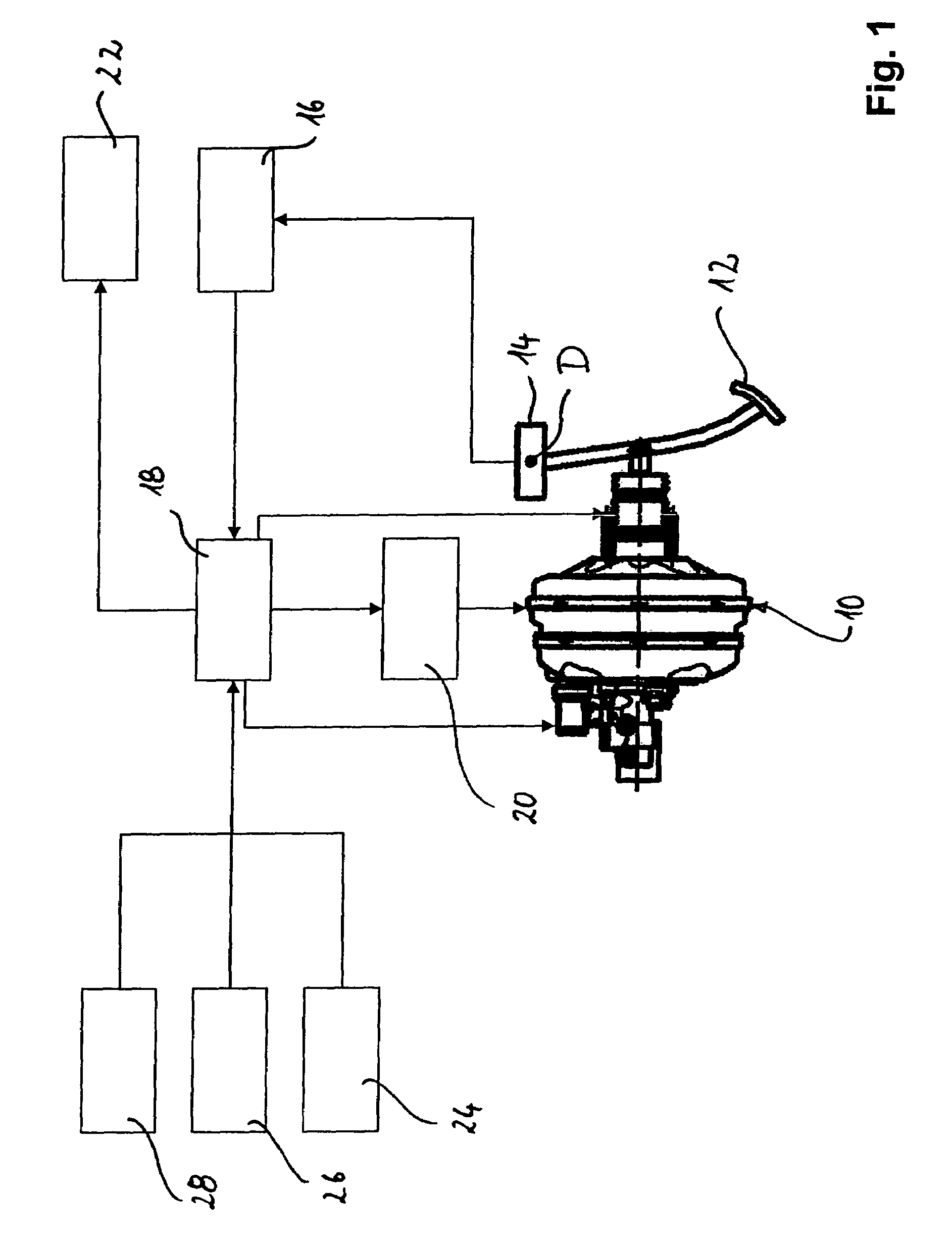
[0034]In FIG. 1 a brake force generator according to the invention is generally denoted by 10 and shown in a diagrammatic overview representation. The brake force generator 10 is connected to a brake pedal 12. A pedal actuation is detected by an angle-of-rotation sensor 14 disposed around an axis of rotation D and is communicated to an angle-of-rotation sensor evaluation device 16. This communicates to an electronic control unit 18 a signal corresponding to the actual pedal actuation. In accordance with the signal characterizing the actual pedal actuation, the electronic control unit 18 activates a vacuum pump 20 as well as further components of the brake force generator 10, as will be additionally explained below. The electronic control unit 18 moreover activates a brake light 22 in response to a detected pedal actuation. The electronic control unit 18 further receives signals from various control systems within the vehicle, such as for example an electronic stability program 24, a...


PUM


Abstract

In a brake force generator for a vehicle hydraulic brake system having a force input element, which is connectable or connected to a brake pedal and displaceable in a base housing of the brake force generator, a master cylinder, in which a primary piston is displaceably guided, wherein the primary piston with the master cylinder delimits a primary pressure chamber for generating a hydraulic brake pressure, an electromagnetic actuating force generating device for exerting an actuating force on the primary piston, and at least one operating position detecting device for detecting the present operating position of the brake force generator, it is provided that the actuating force generating device is controllable in accordance with a brake pedal actuation and that the brake force generator is provided with a central connector, in which contact elements for contacting electric lines to the actuating force generating device and to the operating position detecting device are integrally provided.

Description

CROSS-REFERENCE TO RELATED APPLICATIONS[0001]This application is a continuation of International Application No. PCT / EP2005 / 001325 filed Feb. 10, 2005, the disclosures of which are incorporated herein by reference, and which claimed priority to German Patent Application No. 10 2004 007 659.6 filed Feb. 17, 2004, the disclosures of which are incorporated herein by reference.BACKGROUND OF THE INVENTION[0002]The present invention relates to a brake force generator for a vehicle hydraulic brake system having a force input element, which is connectable or connected to a brake pedal and displaceable in a base housing of the brake force generator, a master cylinder, in which a primary piston is displaceably guided, wherein the primary piston with the master cylinder delimits a primary pressure chamber for generating a hydraulic brake pressure, an electromagnetic actuating force generating device for exerting an actuating force on the primary piston, and at least one operating position dete...

Claims


Application Information

Patent Timeline
Patent Type & Authority Patents(United States)
IPC IPC(8): B60T8/44B60T13/52B60T13/66B60T13/72
CPCB60T13/52B60T13/662B60T13/72B60T13/66
Inventor SCHLUTER, PETER
Owner LUCAS AUTOMOTIVE GMBH
Why Eureka
Try Eureka