Feed pump

a technology of feed pump and bearing, which is applied in the direction of machines/engines, liquid fuel engines, sliding contact bearings, etc., can solve the problems of reducing the efficiency of the feed pump, high friction in the bearing of the impeller, and the impeller and consequently the shaft driving the impeller are subject to a very high load in the radial direction, so as to achieve low flow loss, high efficiency, and high cost-effective

Inactive Publication Date: 2005-09-13
SIEMENS AG
View PDF13 Cites 4 Cited by
  • Summary
  • Abstract
  • Description
  • Claims
  • Application Information

AI Technical Summary

Benefits of technology

[0007]By virtue of this configuration, the forces transmitted to the impeller by the fluid flowing in the feed chambers have, in the radial direction, directions of force which are opposite to one another. The forces consequently cancel one another, so that bearing forces of the shaft driving the impeller can be kept particularly low. The feed pump according to this aspect of the invention therefore has particularly high efficiency. A further advantage of this configuration of the feed pump according to this aspect of the invention is that it has very low wear and therefore has a particularly long useful life.
[0009]The feed chambers of the feed pump according to this aspect of the invention extend over virtually their entire circle diameter when the feed chambers are arranged on opposite end faces of the impeller. As a result, the feed pump has particularly high efficiency.
[0010]According to another aspect of the invention, axial forces can be distributed uniformly over one side of the impeller when vane chambers arranged on the two end faces of the impeller overlap and when the inlet ducts of the feed chambers are arranged on one end face of the impeller and the outlet ducts on the other end face of the impeller. The axial forces acting on the impeller can thereby be supported in a simple way. Furthermore, as a result of this configuration, the feed pump according to the invention has the flow passing through it axially and can therefore be arranged in a particularly space-saving way, for example, in a feed unit for fuel in a motor vehicle.
[0012]According to another aspect of the invention, the axial bearing is constructed in a particularly simple way and can therefore be manufactured particularly cost-effectively when the axial bearing has a ball provided for supporting a shaft driving the impeller.
[0013]The feed pump according to the invention has particularly low flow losses and consequently very high efficiency when the outlet ducts and / or the inlet ducts are arranged so as to point in the radial direction toward the feed chambers.

Problems solved by technology

One disadvantage of the known feed pump is that the impeller and consequently the shaft driving the impeller are subjected to very high load in the radial direction, since the pressure within the feed chamber is substantially higher in the region of the outlet duct than in the -region of the inlet duct.
This leads to very high friction in bearings of the impeller.
Moreover, the friction reduces the efficiency of the feed pump.

Method used


Image

  • Feed pump
  • Feed pump
  • Feed pump

Examples


Embodiment Construction

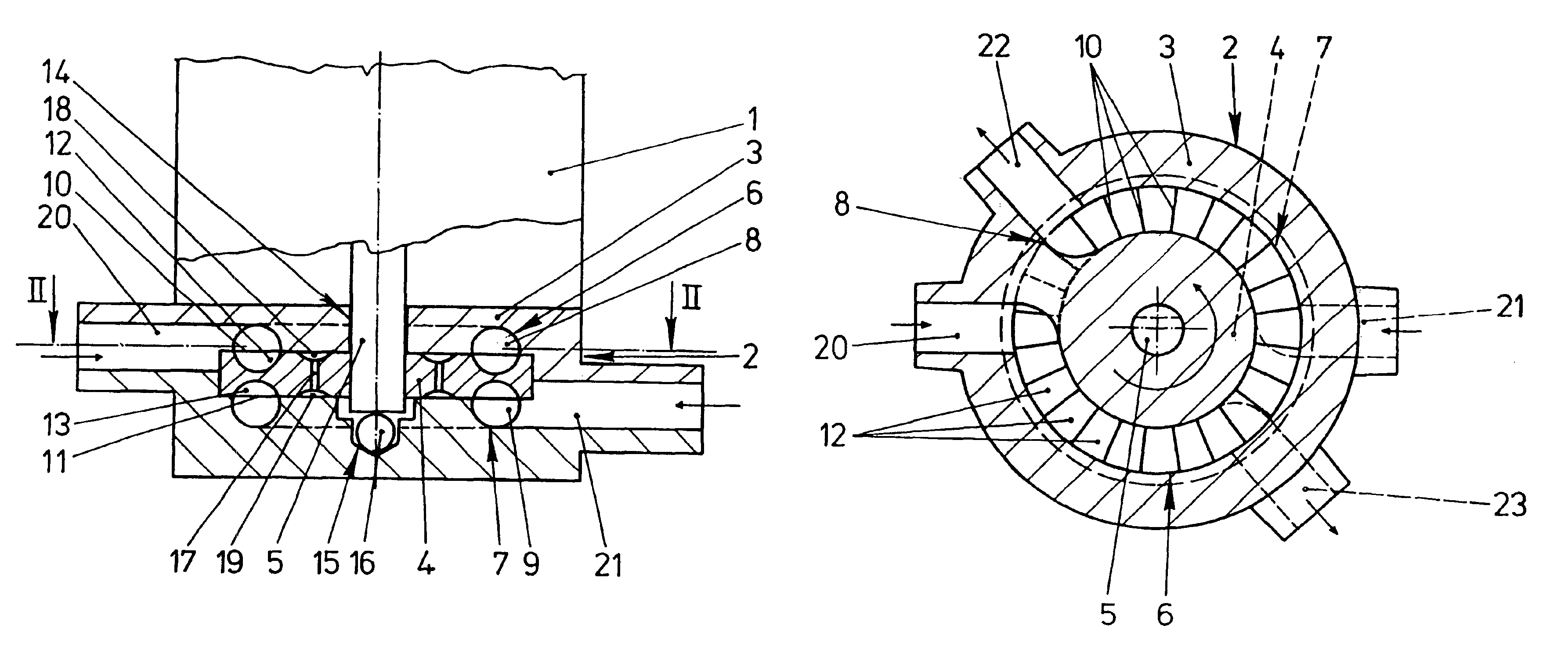
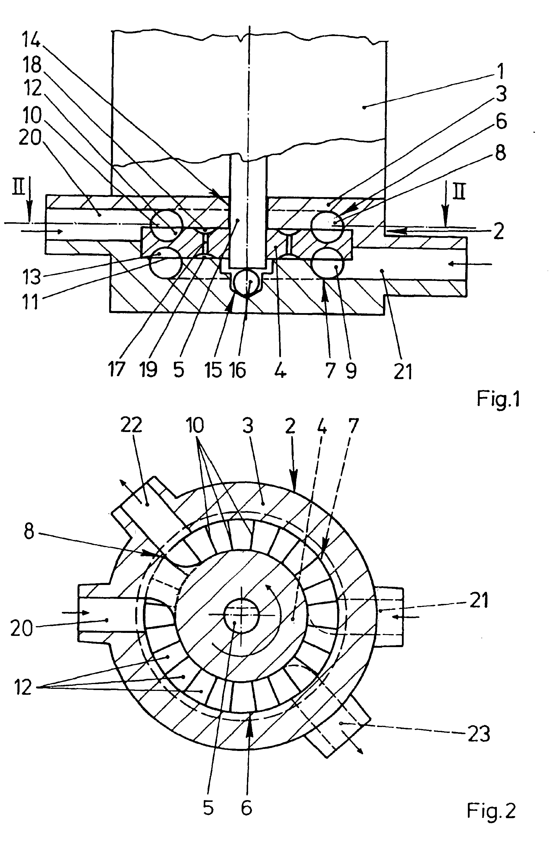
[0018]FIG. 1 shows a feed pump 2 driven by an electric motor 1 and having an impeller 4 rotating in a pump casing 3. The feed pump 2 is designed as a side-channel pump and can be used, for example, for the feed of fuel or windshield washing fluid in a motor vehicle. The impeller 4 is fastened on a shaft 5 of the electric motor 1. The feed pump 2 has two feed chambers 6, 7 separate from one another. The feed chambers 6, 7 have in each case a part-annular channel 8, 9 arranged in the pump casing 3 and vane chambers 12, 13 delimited by guide vanes 10, 11 of the impeller 4. The shaft 5 has, near the electric motor 1, a radial bearing 14 and, below the impeller 4, an axial bearing 15 with a ball 16 arranged in the pump casing 3. The ball 16, like the shaft 5, is hardened. Pockets 18, 19 connected to one another via ducts 17 are worked in the end faces of the impeller 4. The pockets 18, 19 are filled by the leakage of the fluid to be fed and, with the opposite wall of the pump casing 3, f...


PUM


Abstract

The invention relates to a feed pump (2) that is configured as a side-channel pump with a plurality of identically designed feed chambers (6, 7) with outlet channels (22, 23) that are disposed opposite one another, thereby eliminating the radial forces acting upon the impeller (4) of the feed pump (2). The feed pump (2) according to the invention is especially wear-free and has a very high degree of efficiency.

Description

CLAIM FOR PRIORITY[0001]This application claims priority to International Application No. PCT / DE01 / 04675, which was published in the German language on Jun. 20, 2002, which claims the benefit of priority to German Application No. 10062451.0 which was filed in the German language on Dec. 14, 2000.TECHNICAL FIELD OF THE INVENTION[0002]The invention relates to a feed pump with a driven impeller which rotates in a pump casing and which has in its end faces at least one ring of guide vanes delimiting vane chambers, and with at least one part-annular channel which is arranged in the region of the guide vanes in the pump casing and which forms, with the vane chambers, a feed chamber from an inlet duct to an outlet duct.BACKGROUND OF THE INVENTION[0003]Such feed pumps are often used, for example in present-day motor vehicles, for feeding fuel or windshield cleaning fluid and are known from practice. The impeller of the feed pump is fastened on a shaft of an electric motor. The feed pump has...

Claims


Application Information

Patent Timeline
Patent Type & Authority Patents(United States)
IPC IPC(8): F04D5/00F04D29/046F04D29/24F04D29/42F16C17/08
CPCF04D5/006
Inventor PENZAR, ZLATKOWILHELM, HANS-DIETER
Owner SIEMENS AG
Why Eureka
Try Eureka