
Eureka
For R&D, Eureka makes reading and utilizing patents & technical documents easy.
Eureka AIR
Designed for self-driven R&D workflows. Generate viable solutions, solve complex R&D challenges, empower your innovation with AI.

Eureka Materials
Designed for material experts only. Revolutionize your material R&D, from search, analyze, to developing new materials.

TechResearch
Generate reliable direction feasibility study reports for your R&D in just a few steps.

TechSeek
Discover and master advanced knowledge NOW. Basics, ideas, possibilities, all at once.

TechMind
As an expert in R&D Theories, TechMind can generates customized viable solutions instantly.

TechRisk
Analyze your overall solution with one click, know your potential R&D risks in advance.

TechMonitor
Get weekly tech updates, stay abreast of the latest tech innovations and key insights.
Septal-pericardial heart valve implant anchor
- Summary
- Abstract
- Description
- Claims
- Application Information
AI Technical Summary
Benefits of technology
Problems solved by technology
Method used
Image

Examples
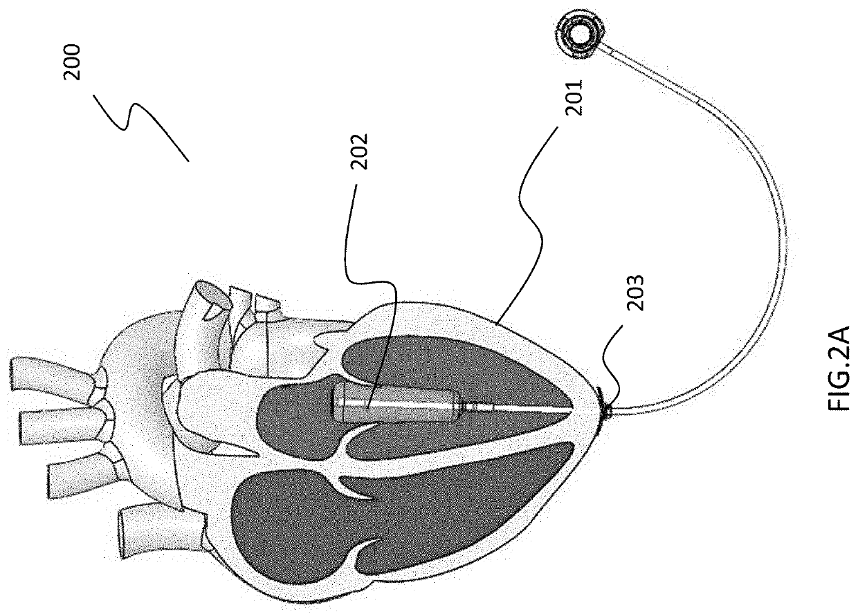
embodiment 200
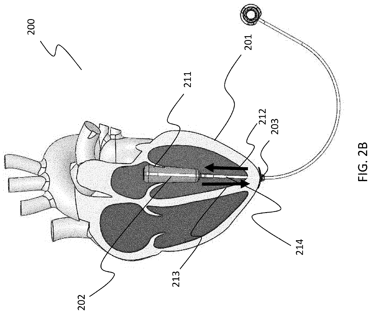
[0045]Referring to FIG. 2B, the embodiment 200 of FIG. 2A is depicted, along with the forces created by the anchor 214, in accordance with an embodiment. In some embodiments, the pumping action of the heart 201 combined with the action of the mitral valve 211 with respect to the implanted spacer 202, during refilling of the left ventricle, provides a force 212 that pulls the anchor point (i.e., the apex 203 of the heart 201), which prevents expansion 213 of the heart.
[0046]In some embodiments, the location and design of the anchor for the spacer may be chosen to enhance reverse remodeling. In some embodiments, such as depicted in FIG. 3, one or more anchors that provide cross septal—pericardial forces 301 on the heart 300 may aid in reverse remodeling. Such forces would not only aid in supporting the septum and pericardium against the pressure created during pumping, but also aid in their movement inwards, such as during healthy beating. Therefore, the opposite ventricle would also ...
embodiment 600
[0049]In some embodiments, the anchor connections to the spacer may include elastic members (e.g., springs or expandable materials) to maintain tension as reverse remodeling occurs. FIG. 6A depicts a spacer 601 featuring anchors 602, each anchor comprising a coil 603, in accordance with an embodiment 600. In some embodiments, the elastic member may be pre-tensioned. In some embodiments, the pre-tensioned elastic member may be coated in a slow-absorbable or dissolvable material (e.g. polyglycolic acid, polylactic acid, polydioxanone, caprolactone, and / or catgut). Briefly referring to FIG. 6B, in some embodiments, the coils may be released and allowed to transform from a compressed state 650 to an expanded state 660. Alternatively, in some embodiments, the coils may be released and allowed to transform from an expanded state 660 to a compressed state 650. As remodeling is reversed, the heart may reshape, requiring anchors having different lengths. As such, in such embodiments, the tim...
PUM
| Property | Measurement | Unit |
|---|---|---|
| Length | aaaaa | aaaaa |
| Time | aaaaa | aaaaa |
| Elasticity | aaaaa | aaaaa |
Abstract
Description
Claims
Application Information
 - R&D Engineer
- R&D Manager
- IP Professional
- Industry Leading Data Capabilities
- Powerful AI technology
- Patent DNA Extraction
Browse by: Latest US Patents, China's latest patents, Technical Efficacy Thesaurus, Application Domain, Technology Topic, Popular Technical Reports.
© 2024 PatSnap. All rights reserved.Legal|Privacy policy|Modern Slavery Act Transparency Statement|Sitemap|About US| Contact US: help@patsnap.com