

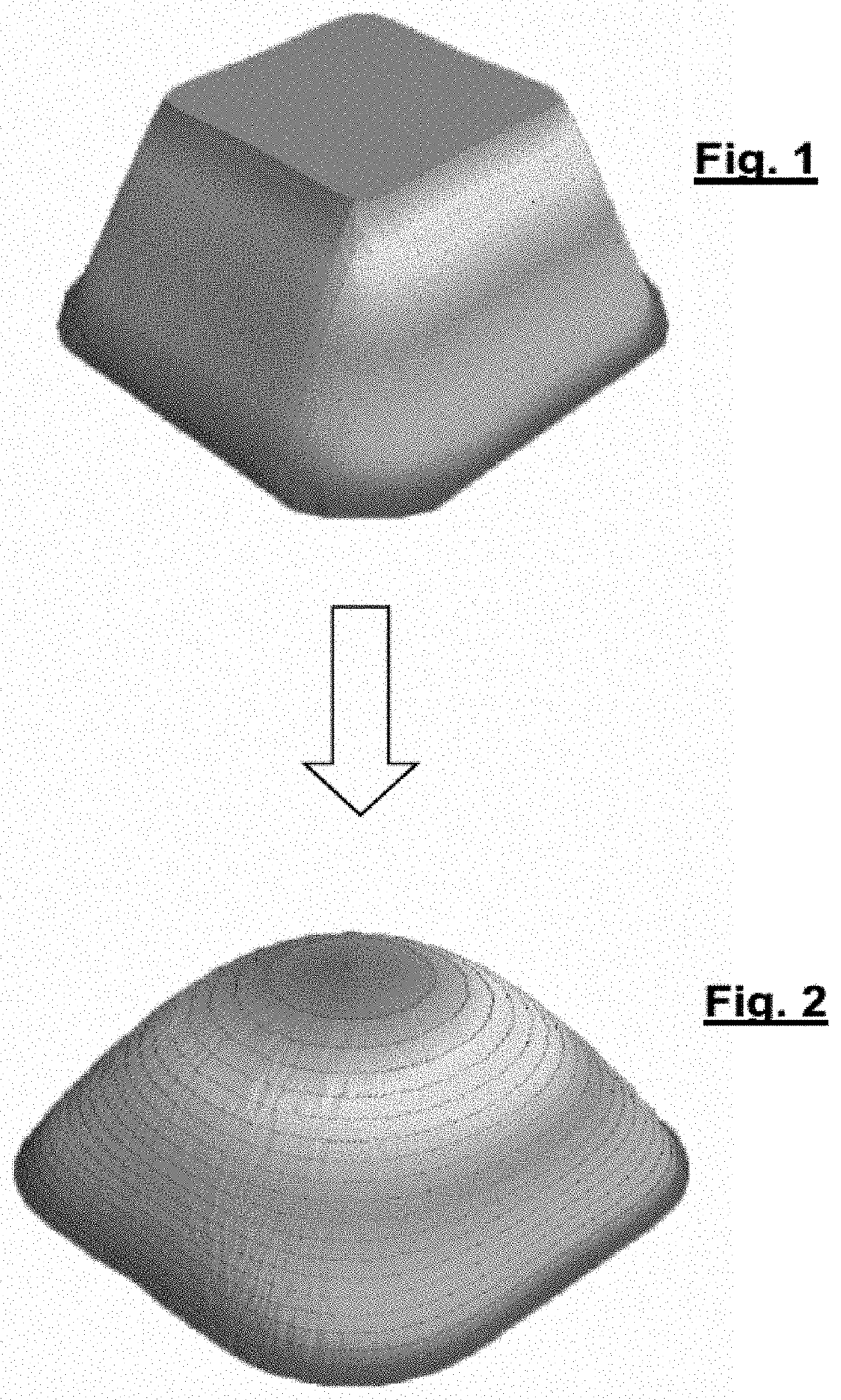
Predicting the shape of a three-dimensional object which is subjected to a diffusion process
a diffusion process and object technology, applied in the field of manufacturing three-dimensional objects, can solve the problems of difficult to determine the shape of the object after reflow in advance, and it is necessary to carry out long and costly test runs
- Summary
- Abstract
- Description
- Claims
- Application Information
AI Technical Summary
Benefits of technology
Problems solved by technology
Method used
Image

Examples
first embodiment
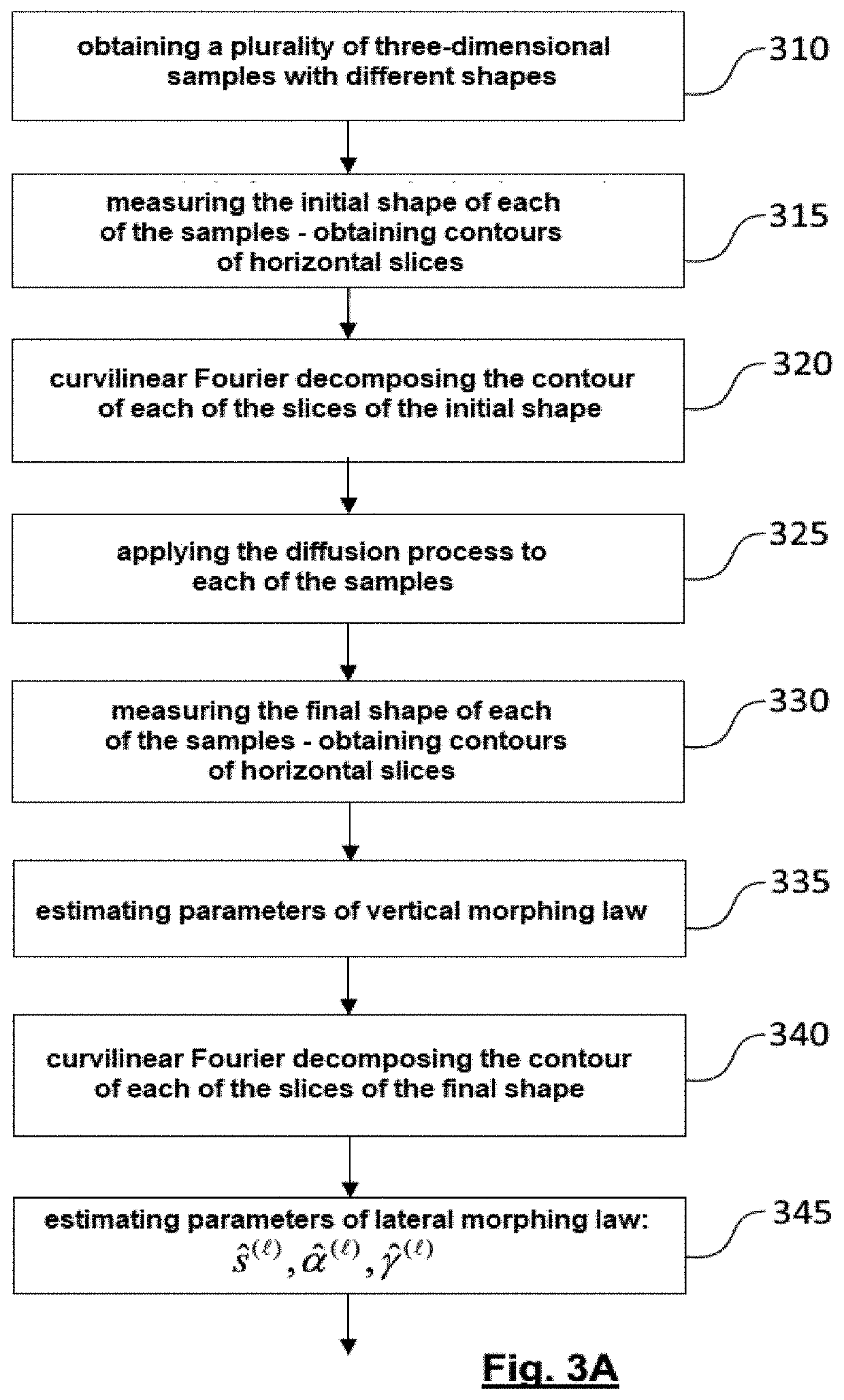
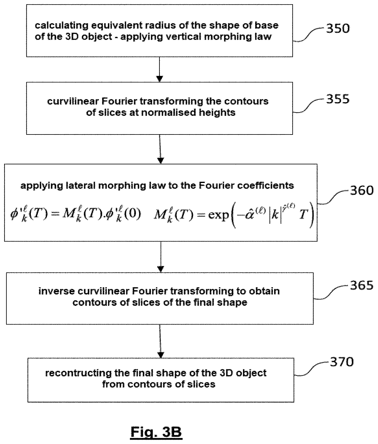
[0063]FIGS. 3A-3B represent the flowchart of a method for predicting, the shape of a three-dimensional object that has undergone a diffusion process for a predetermined period of time.
[0064]The prediction method first comprises a calibration phase comprising steps 310-345 in FIG. 3A.
[0065]In step 310, a plurality of samples of three-dimensional objects with different heights are available. These samples also advantageously have different profiles.
[0066]In step 315, the initial shape of each of the samples is measured, for example using an atomic force microscope (AFM). The height of each sample is measured and divided into L intervals, each interval defining a horizontal slice of the object located at a normalised height, . From the measurement of the initial shape, the contour of each slice =1, . . . , L is obtained. In step 320, a curvilinear Fourier decomposition of the contour of each of these slices is performed.
[0067]In step 325, the diffusion process is applied to the diffe...
second embodiment
[0097]According to the invention, the representation of the contours of the slices of the three-dimensional object does not use a curvilinear Fourier series decomposition but a method of level surfaces, expanded in Fourier coefficients. In general, methods of level surfaces allow the evolution of an interface to be represented. A one-dimensional interface Γ or level line, bounding at instant t a region C in a plane is defined by an equation of the type:
F(x,y,t)=0 (24)
where the function F is a smooth function, positive inside the curve Γ (thus on Ω) and negative outside it.
[0098]A given instant t0 is now considered and the function defining the curve Γ at that instant is noted ƒ(x,y). The knowledge of a number of points belonging to this curve and the normals to the curve at this point make it possible to calculate the (spatial) Fourier coefficients of the function ƒ(x,y).
[0099]Indeed, given a set of N points Pi, i=1, . . . , N, with coordinates (xi,yi) belonging to the curve Γ and ...
PUM
| Property | Measurement | Unit |
|---|---|---|
| Shape | aaaaa | aaaaa |
| Height | aaaaa | aaaaa |
Abstract
Description
Claims
Application Information