


Quick Research
Generate reliable direction feasibility study reports for your R&D in just a few steps.

Technical Q&A
Discover and master advanced knowledge NOW. Basics, ideas, possibilities, all at once.

Find Solutions
As an expert in R&D theories, this can generate solutions to your technical problems instantly.

Evaluate Feasibility
Analyze your overall solution with one click, know your potential R&D risks in advance.

Monitor Landscape
Get weekly tech updates, stay abreast of the latest tech innovations and key insights.
Wingtip device for an aircraft
- Summary
- Abstract
- Description
- Claims
- Application Information
AI Technical Summary
Benefits of technology
Problems solved by technology
Method used
Image

Examples
first embodiment
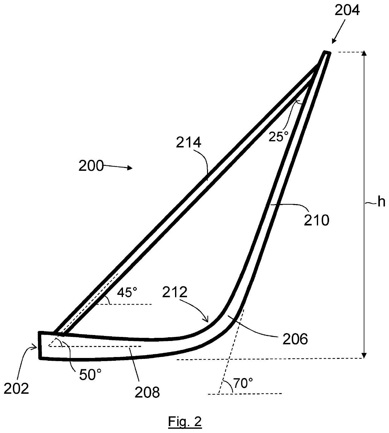
[0103]FIG. 2 shows a wing tip device 200, of a first embodiment, viewed in the longitudinal axis of the aircraft. The device 200 has a root 202 at its inboard end and a tip 204 at its outboard end. The device 200 comprises a lower section 206 which has the general profile of a blended winglet. The lower section 206 in this case has a shape corresponding generally to that of a “sharklet” for the Airbus A320 Neo. Thus the section 206 comprises a generally horizontal inbound portion 208 that is joined to a canted outbound portion 210, via a blended region 212. The dihedral angle of the canted outdone portion is about 70° for at least 1,000 mm of its extent. The height, h, of the tip 204 above the horizontal position of the inbound portion 208 is at least 2,000 mm. Each lower section 206 has a mass of the order of at least 80 kg.
[0104]The device 200 comprises an upper section 214 which acts as a strut extending from a location at or directly adjacent to the root 202 of the device to a l...
second embodiment
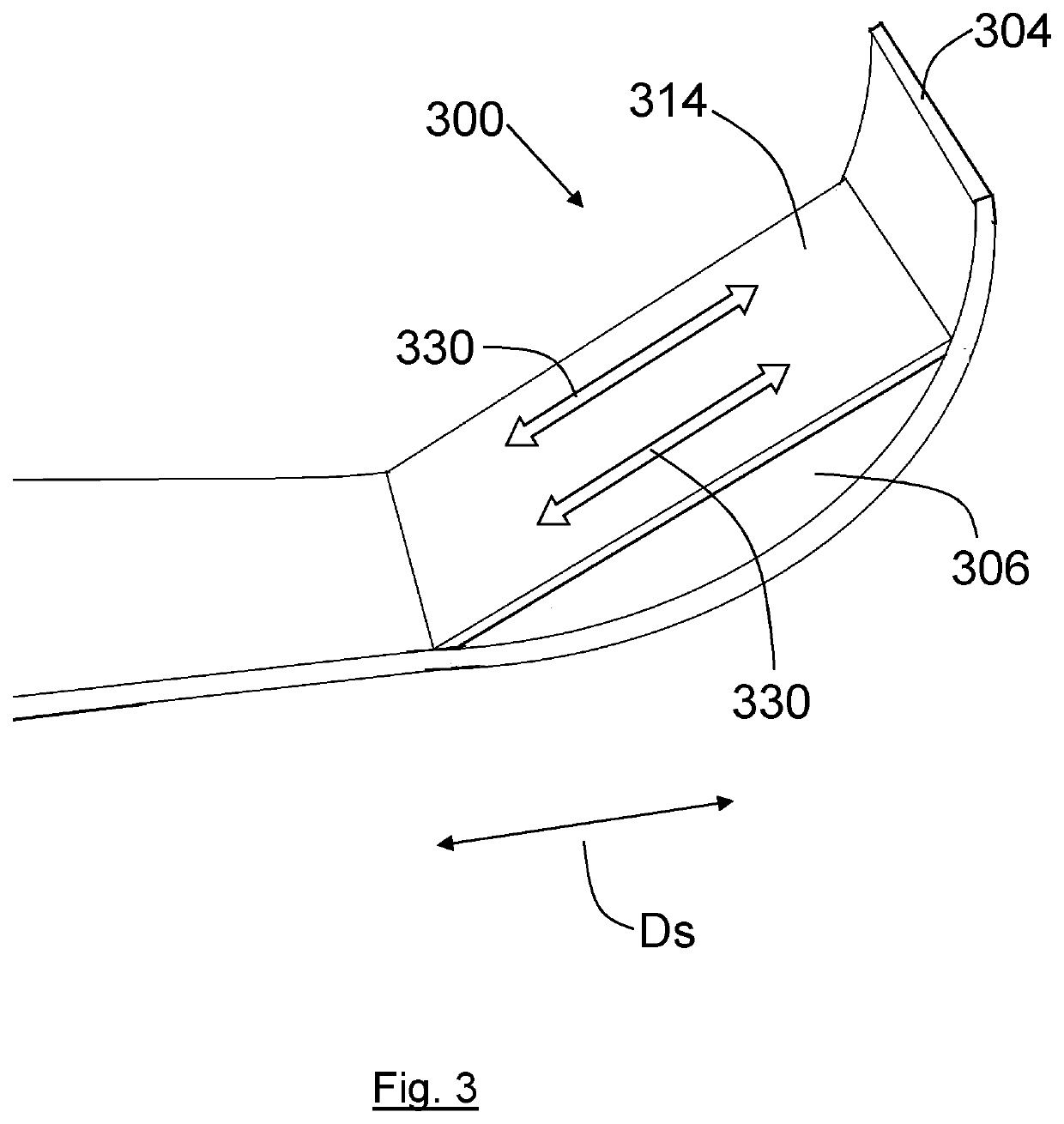
[0107]FIG. 3 shows (with a highly schematic diagram) a perspective view of a device 300 which has substantially the same shape and configuration as the device of FIG. 2. The reference numerals as used in FIG. 3 will refer to the same parts as the reference numerals used in FIG. 2, but will start with a “3” instead of starting with a “2”. The upper section 314 of the device 300 includes two elements 330, which are arranged to exert varying forces within the structure of the upper section 314 in a direction substantially parallel with the spanwise direction Ds of the wing, when viewed in plan. (It will be understood that in the present context the spanwise direction at a given location is taken as the mean direction of the leading and trailing edges of the wing when viewed in plan, and not necessarily perpendicular to the longitudinal direction of the aircraft). In this embodiment, the elements 330 may be in the form of hydraulic actuators. By means of varying the force exerted by ea...
third embodiment
[0111]FIG. 5 shows the wingtip device 400 of the third embodiment in a highly schematic manner. The upper section 414 comprises two integrally formed cable systems 430 which are arranged within the structure of the upper section 414 in such a way as to enable the shape of the upper section 414 to be deformed elastically under the control of the cable systems 430. In this embodiment, the integrated cable systems 430 are designed to be adjusted by ground crew when attending to the aircraft when on the ground and a stationary. Once the geometry of the wingtip device 400 has been set up by ground crew by means of making adjustments to the integrated cable systems 430 and the aircraft is moving, the setup of the wingtip device, in so far as its global geometry is concerned, is a fixed and cannot be altered or controlled by the pilot during flight. FIG. 5 shows the wingtip device 400 in a first configuration, in which the tension in each cable system is approximately equal, at about 250 N...
PUM
 Abstract
Description
Claims
Application Information
 - R&D Engineer
- R&D Manager
- IP Professional
- Industry Leading Data Capabilities
- Powerful AI technology
- Patent DNA Extraction
Browse by: Latest US Patents, China's latest patents, Technical Efficacy Thesaurus, Application Domain, Technology Topic, Popular Technical Reports.
© 2024 PatSnap. All rights reserved.Legal|Privacy policy|Modern Slavery Act Transparency Statement|Sitemap|About US| Contact US: help@patsnap.com