This helps you quickly interpret patents by identifying the three key elements:
Problems solved by technology
Method used
Benefits of technology
Benefits of technology
[0008] It is another object of the present invention to provide a milling tool that requires less force for running the cutter head while performing the required cuts in a work piece.
[0011] When the body engages a work piece and is rotated, at least two splinters are formed with each quarter-turn of the milling head. The cutting planes are separated by a connecting plane that does not perform the cut but facilitates creation of a plurality of shorter distinct splinters. The splinters have different cutting depth allowing creation of a smooth, even cut. The splinters have an optimized profile, with a better proportion between the width and the length that is possible with conventional cutting tools.
[0013] By forming shorter splinters with each cutting plane, the tool of the present invention allows elimination of clogging or jamming of a cutting or milling machine, reduces wear on the cutting machine, while performing the same depth cuts, eliminates vibration or clatter and create a deeper cut than is possible with conventional indexable tips.
Problems solved by technology
In conventionally used cutter head designs, the created shavings are long, curled splinters that tend to clog the cutting area as the machine is driving the cutting head.
The tool edge cutting was an improvement over older designs, but still was limited in its basic capacity to reduce the force necessary for creating certain cutting profiles.
By using a cutting tool that has one cutting edge, one cannot raise the speed of operation without creating clatter, adversely affecting the quality of the cut surface and wearing the tips and the milling machine much faster.
Method used
Image
Click on the blue label to locate the original text in one second.
Reading with bidirectional positioning of images and text.
Examples
first embodiment
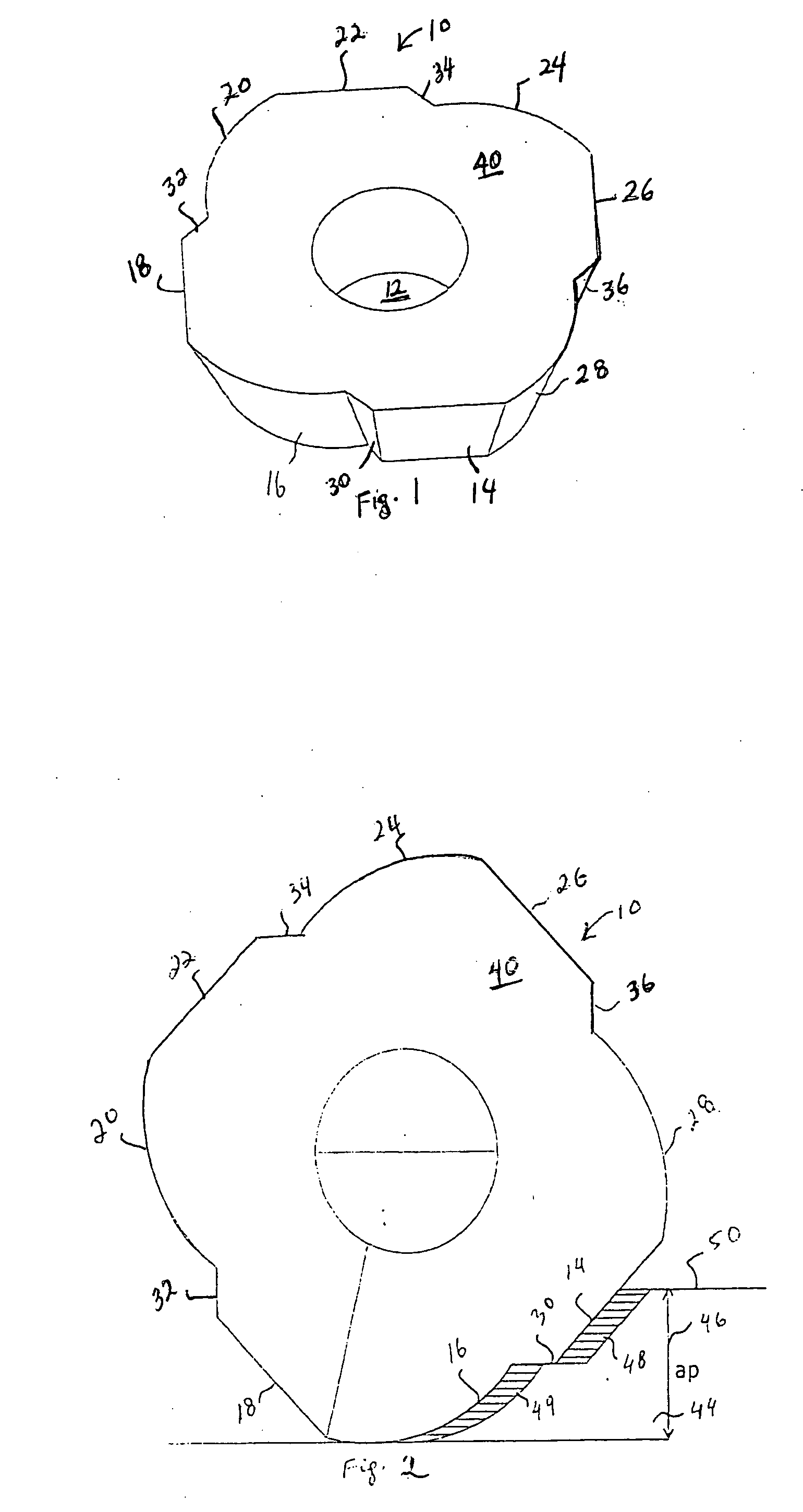
[0034] Turning now to the drawings in more detail, numeral 10 designates a cutting tool body in accordance with the present invention. The cutting tool, or indexable tip body 10, is formed as an irregularly-shaped body. The cutting body is a solid body with four sides and eight cutting planes designated by numerals 14, 16, 18, 20, 22, 24, 26, and 28. The planes 14, 18, 22, and 26 are flat surfaces which are integrally connected to the adjacent rounded planes 6, 20, 24, and 28 by inclined connecting surfaces 30, 32, 34, and 36.
[0035] The cutting body 10 has a top, generally flat surface 40 and a bottom, generally flat surface 42. The surfaces 40 and 42 provide vertical limits to the extension of the cutting planes 14, 16, 18, 20, 22, 24, 26, and 28. In operation, the tip 10 is clamped on a milling head in a conventional manner, and the central opening 12 facilitates this step.
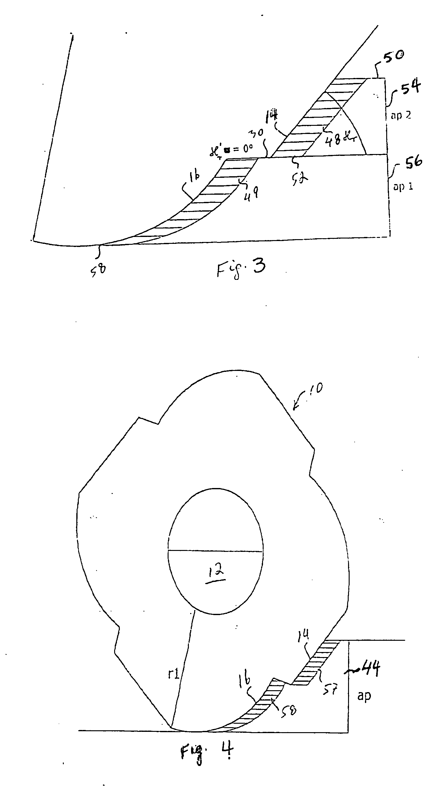
[0036] As shown in FIGS. 2 and 3, a work piece 44 is being cut by the cutting planes of the cutting body 10....
second embodiment
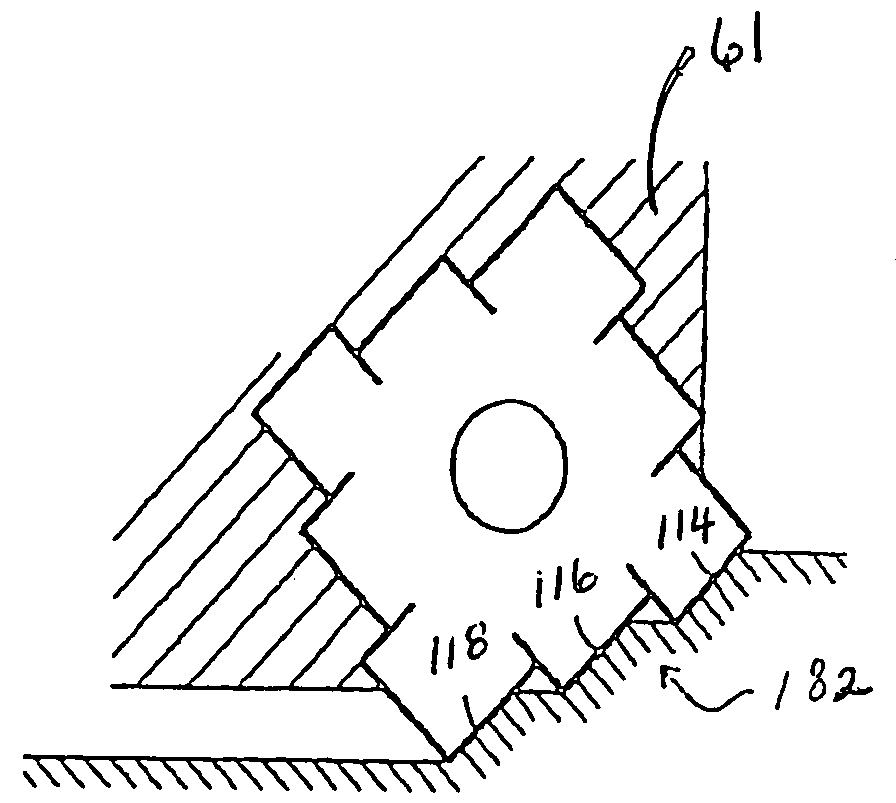
[0041] Turning now to the second embodiment shown in FIGS. 6-14, the cutting body 60 is shown to have four sides and a central opening 62. The central opening 62, similarly to the opening 12, is adapted to facilitate clamping of the body 60 on a milling head 61 (FIG. 8). Each side of the cutting tool body 60 has three irregularly-shaped blocks that have cutting edges. There are a total of eight blocks 64, 66, 68, 70, 72, 74, 76 and 78, which are attached to each other. Each side 80, 82, 84 and 86 of the body 60 has three blocks.
[0042] With reference to the side 80, the blocks 64, 66 and 68 have respective staggered top surfaces 94, 96 and 98 and staggered vertical planes 104, 106 and 108. The body 60 has a bottom, non-cutting surface 63 (FIGS. 9 and 10). A line of connection between the vertical surface 104 and the top surface 94 forms a cutting edge 114; the line of connection between the plane 106 and the top surface 96 forms a second cutting edge 116; and the line of connection b...
third embodiment
[0053] Turning now to FIGS. 15—18, the cutting body 60 has four sides, each with four cutting edges, such as edges 152, 154, 156 and 158 identified in FIGS. 15-18. The cutting planes, or edges 152, 154, 156 and 158 are connected by inclined connecting planes 160, 162 and 164. The three other sides of the body 60 is similarly provided with four cutting planes, which are connected to adjacent cutting planes by inclined surfaces.
[0054]FIG. 15 illustrates position of the body 60 engaging a work piece 166 with four cutting surfaces that form cutting edges along the areas of contact between the body 60 and the work piece 166. In this embodiment, the cutting tool creates four unequal length splinters 170, 172, 174, and 176. The profiles of the splinters differ from a conventional one piece profile that would extend roughly from a top surface 150 to the bottom surface 182 of the work piece 166. As can be better seen in FIG. 16, the length of the splinters can vary, depending on the geometry...
PUM
Property
Measurement
Unit
Length
aaaaa
aaaaa
Time
aaaaa
aaaaa
Force
aaaaa
aaaaa
Abstract
A cutting tool for a milling, drilling or turning machine has a body with a plurality of sides and a central opening. Each side has a perimeter along which cutting planes or edges are formed. Each side has at least two such cutting planes or edges. The planes may have a straight or curved profile, or a combination of straight and curved profiles along one side. The tool may have a plurality of such cutting planes formed along each side of the tool body. The cutting planes may be located at different levels in relation to each other, entering a work piece in sequence, or may be aligned to enter the work piece simultaneously. Preferably, the cutting planes are staggered in two directions—in a feeding direction and in a cutting direction. By dividing each surface being cut into a plurality of segments, the cutting tool creates a plurality of distinct shavings, or splinters that have shorter length in comparison with conventional splinters formed by indexable tips. Shorter cuts require less cutting force, which saves wear on the cutting tool and the machine. At the same time, the cuts can be made deeper and smoother when dividing the cutting surface into a plurality of segments.
Description
BACKGROUND OF THE INVENTION [0001] The present invention relates to a metal-cutting or milling tool. Such tools are extensively used in the metal working technology for cutting, polishing and creating grooves in a metal work piece. [0002] Conventional milling tools comprise a body rotatable around a central axis; the body being provided with a cutter head that has one or more cutting blades, or cutting tips. As the cutting tips shave or cut off layers of metal, splinters or shavings are created. In conventionally used cutter head designs, the created shavings are long, curled splinters that tend to clog the cutting area as the machine is driving the cutting head. [0003] Milling, drilling or turning machines provide for a rotating cutting tool. In some cases, a work piece being cut is rotated. The term “indexable tip” designates a cutting tool for milling, drilling or turning metal. Indexable tips are conventionally clamped in tool holders, such milling heads or drilling heads. The t...
Claims
Application Information
Patent Timeline
Application Date:The date an application was filed.
Publication Date:The date a patent or application was officially published.
First Publication Date:The earliest publication date of a patent with the same application number.
Issue Date:Publication date of the patent grant document.
PCT Entry Date:The Entry date of PCT National Phase.
Estimated Expiry Date:The statutory expiry date of a patent right according to the Patent Law, and it is the longest term of protection that the patent right can achieve without the termination of the patent right due to other reasons(Term extension factor has been taken into account ).
Invalid Date:Actual expiry date is based on effective date or publication date of legal transaction data of invalid patent.

