
Method and system for controlling the material flow of objects in a conveyor system of a real warehouse

Pending Publication Date: 2022-01-27
DEMATIC
View PDF0 Cites 0 Cited by
  • Summary
  • Abstract
  • Description
  • Claims
  • Application Information

AI Technical Summary

Benefits of technology

The present invention offers a way to reduce image recognition outlays in warehouses and improve conveyor performance by controlling virtual models instead of real-time image data. This simplifies material flow control and increases the efficiency of the installed conveyor equipment. Additionally, image sensors can be strategically placed to monitor and control the material flow at critical points, even without a large number of sensors. This saves computing power and reduces the deployment of specialist PLC programmers. Overall, the invention improves operational efficiency and performance capabilities.

Problems solved by technology

Therefore, this requires a considerable amount of outlay.
The corresponding costs for material, installation, commissioning and programming as well as maintenance constitute a considerable portion of the total costs of the installation, wherein the control system generally costs more than the mechanical system.
However, in larger installations this involves considerable outlay for real-time processing and evaluation of the image data, in particular image recognition.

Method used


Image

  • Method and system for controlling the material flow of objects in a conveyor system of a real warehouse
  • Method and system for controlling the material flow of objects in a conveyor system of a real warehouse

Examples


Embodiment Construction

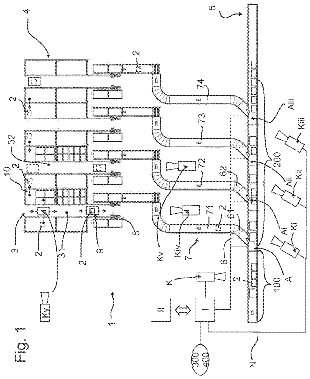
[0031]FIG. 1 shows a plan view of a part of a central warehouse with a conveyor system 1 for placing packets 2 into storage in storage rack aisles 3 which are formed by storage racks 4 which are arranged in parallel with and opposite each other and have a plurality of levels.

[0032]The conveyor system 1 includes a distribution path 5 which conveys packets 2 inwards and outwards. Paths 7 into and out of storage are arranged between the distribution path 5 and the storage racks 4. These paths are connected to the distribution path 5 by introducing and discharging areas 6 and are connected to the storage rack aisles 3 via goods lifts 10. Adjacent paths 71 and 72, 73 . . . into and out of storage are arranged in parallel with each other.

[0033]The packets 2 are transported by the goods lifts 8 from the into-storage paths 7 into the rack levels of the storage racks 4 or from the rack levels to the out-of-storage paths 7. The packets 2 are transported within the rack levels of the storage r...


PUM


Abstract

A method for controlling the material flow of goods to be conveyed in a conveyor system of a real warehouse by a virtual three-dimensional model, for which purpose the conveyor system of the real warehouse is virtualized in a central computer, for which purpose a virtual three-dimensional model of the real conveyor system having the dimensions of the individual conveyor components and the movement parameters thereof, including the actuator properties and the identity, shape and position of the goods to be conveyed, is stored, and the conveyor system of the real warehouse is centrally controlled from the virtual model, images of the goods to be conveyed in the real conveyor system are cyclically captured by sensors, and the virtual model is cyclically compared with the reality on the basis of the recorded images.

Description

CROSS REFERENCE TO RELATED APPLICATION[0001]The present invention claims the priority benefits of International Patent Application No. PCT / EP2019 / 081995, filed Nov. 20, 2019, and claims benefit of German patent application DE 10 2018 130 206.1, filed on Nov. 28, 2018.BACKGROUND AND FIELD OF THE INVENTION[0002]The invention relates to a method for controlling the material flow of objects in a conveyance technique of a real warehouse.[0003]In the case of warehouses within the field of internal logistics or supply and distribution centers etc., it is generally known to control and regulate the material flow of items on the conveyance techniques through the use of local sensors and local decentralized controls (PLCs) which recognize or determine the items and their position.[0004]For instance, in order to actuate drives in such conveyance techniques (actuators) the position of the goods being conveyed (items) must be reliably determined. This takes place typically with the aid of light ...

Claims


Application Information

Patent Timeline
IPC IPC(8): B65G43/08B65G1/137
CPCB65G43/08B65G2203/041B65G2203/0233B65G1/1371G06Q10/08
Inventor MEURER, HANS CHRISTOPH
Owner DEMATIC
Learn More