
Extrusion system comprising a screw changing device

Inactive Publication Date: 2004-10-19
BERSTORFF GMBH
View PDF9 Cites 3 Cited by
  • Summary
  • Abstract
  • Description
  • Claims
  • Application Information

AI Technical Summary

Benefits of technology

is to develop an extrusion system of the generic type in such a way as to substantially reduce the outlay required for converting the extrusion system from processing of one material to processing of another material with different properties. The aim therefore is to permit rapid changing of material while at the same time maintaining a high product quality and high productivity.
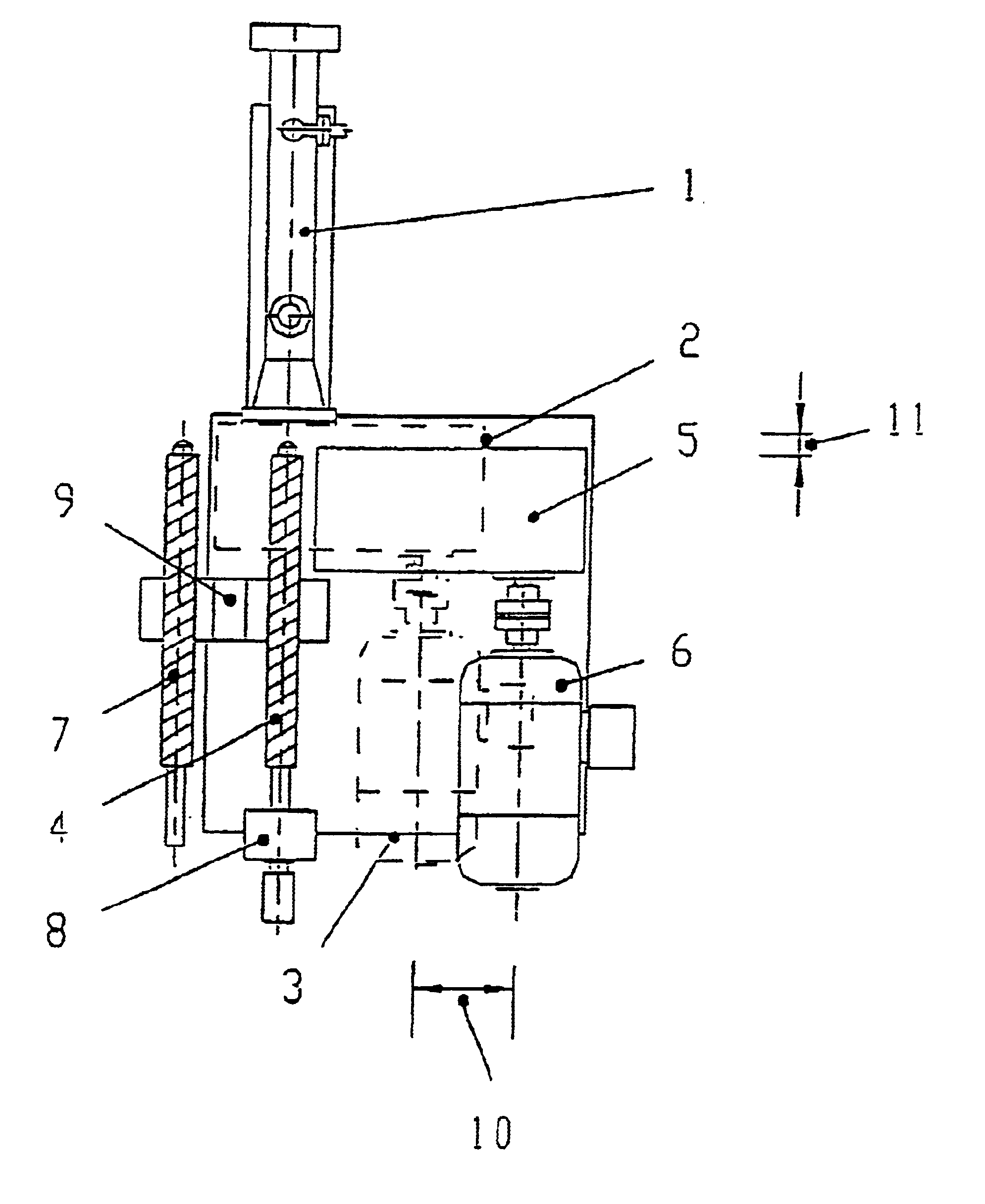
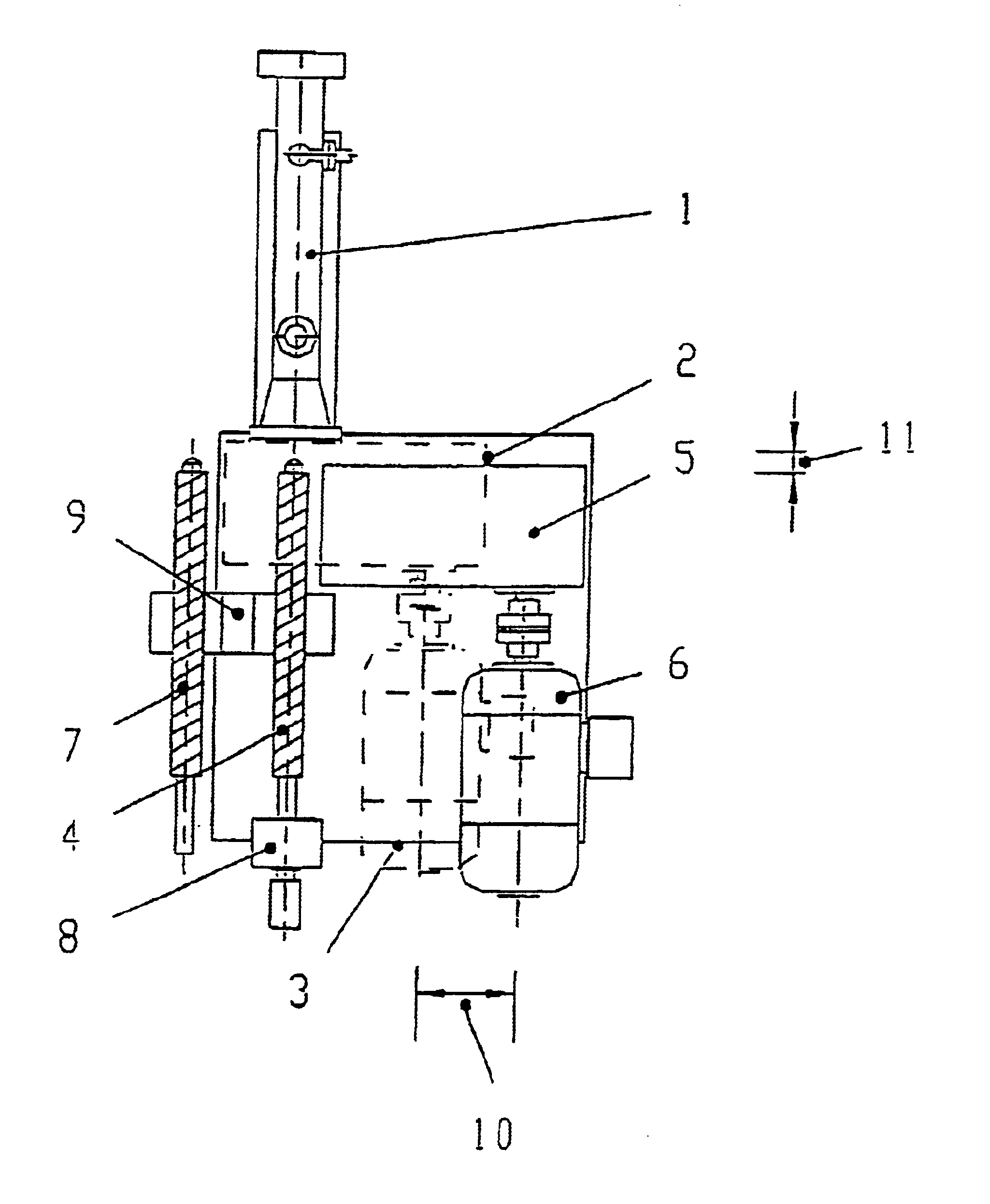
For an extrusion system of the generic type, the gearing is mounted on a gearing carriage configured to draw the gearing back a short distance in the direction of the axis of the screw in order to decouple the coupling. The carriage can be pivoted or can be moved transversely to the axis of the screw so that the gearing with the coupling can be moved away from the screw so that the screw can be withdrawn completely from the extruder counter to the feed direction of the screw. A screw-changing device is provided by which the existing screw of the extruder can be received and can be replaced by another screw in the screw-changing device.
The screw-changing device for mechanized exchange of the screw can be designed as a stationary or movable screw magazine, with a maneuvering device for withdrawal and insertion of a screw. In the simplest case, the screw magazine is designed with a rotatable double arm, where one arm is intended to receive the screw to be replaced, and the other arm carries the new screw. The screw magazine is preferably configured as a revolver magazine or paternoster magazine and is thus suited to receive a large number of replacement screws. This ensures a high degree of flexibility in terms of the processing of a correspondingly large number of different materials.
In principle it is possible for the movements of the gearing carriage and of the maneuvering device to be executed by an operator. In this case, the configuration of the extrusion system according to the invention relieves the operator at least from the heavy work during dismantling of the old screw and fitting of the new screw. In addition, the necessary movements of the screws can take place in set tracks, so that the time needed for screw-changing is considerably reduced.
Still greater time savings can be made if the gearing carriage and if appropriate also the screw-changing device are each provided with a motor drive. This drive is preferably actuated by an electronic control means whose program memory is preferably set up for fully automatic screw-changing.

Problems solved by technology

However, this means that, in the processing of the individual materials, such a screw or pair of screws generally has to operate some way from the actual operating optimum.
This may entail a corresponding decrease in product quality and / or a reduced production rate.
For processing plastics batches of different materials in smaller quantities, the use of special screws for the particular material involves a disproportionately high operating outlay since changing the screws has hitherto generally required a relatively high cost, particularly in the form of the shutdown of the production plant.
These separate machines not only take up a corresponding space, but are also in many cases characterized by a relatively low degree of utilization.
This ultimately means that the processing of smaller batches is relatively expensive compared to the main production quantities of the standard products.
In the case of longer screws, this solution would require an extremely long construction space.

Method used


Image

  • Extrusion system comprising a screw changing device
  • Extrusion system comprising a screw changing device

Examples


Embodiment Construction

An extruder 1 which is designed as a single-screw extruder and whose downstream equipment is not shown here has a gearing 2 at its end remote from the extruder head, and a motor 3 is flange-mounted onto this gearing 2 in order to drive the extruder screw. The gearing 2, whose working position is indicated by broken lines in the figure, is equipped with a coupling (not shown) for attachment of the upstream end of the extruder screw. The gearing 2, with the motor 3 flange-mounted thereon, is mounted on a gearing carriage (of which no details are shown here). To disconnect the coupling of the gearing 2 from an extruder screw still present in the extruder 1, the gearing carriage can be drawn back a short distance counter to the feed direction of the extruder screw, for example after releasing a quick-action clamp with which the gearing 2 is connected securely to the extruder 1 during normal system operation. This decoupling path has been indicated by reference number 11 in the figure. A...


PUM

PropertyMeasurementUnit
Distanceaaaaaaaaaa

Abstract

At least one screw of a screw-type extruder drive-connected via a coupling to a gearing that is driven by a motor, the coupling being able to be coupled to and decoupled from the screw. A gearing carriage is provided which is configured such that the gearing can be drawn by a short distance on the gearing carriage in the direction of the longitudinal axis of the screw in order to decouple the coupling, and which gearing carriage can be swiveled or can move transverse to the longitudinal axis of the screw. The gearing with the coupling can be moved away from the screw to such an extent that the screw can then be withdrawn completely from the extruder counter to the feed direction of the screw, and a screw-changing device is provided by which the existing screw of the extruder can be received and can be replaced by another screw located in the screw-changing device.

Description

1. Field of the InventionExtrusion system comprising a screw-changing device The invention relates to an extrusion system comprising at least one screw-type extruder whose at least one screw is drive-connected via a coupling to a gearing that is driven by a motor, said coupling being able to be coupled to and decoupled from the screw.2. Description of the Related ArtExtrusion systems are used particularly in the plastics industry for production of plastic products and also for compounding of plastics, i.e. for manufacturing intermediate products made up of different substances. Extrusion systems for the latter purpose are also referred to as compounding systems and in many cases have extruders with two or more screws which mesh with one another. In these compounding systems, additives such as dyes or fiber materials, for example, are mixed into the plastics raw material and distributed as uniformly as possible therein. Given the wide variety of thermoplastics in particular, and the ...

Claims


Application Information

Patent Timeline
IPC IPC(8): B29C47/08F16H35/00B29B7/38B29B7/58B29C45/14B29C48/03B29K101/00
CPCB29C47/0866B29C47/082B29C47/0009B29C48/03B29C48/2561B29C48/266
Inventor CHSZANIECKI, SIEGFRIED
Owner BERSTORFF GMBH
Learn More