
Method of modeling part of shoe and method of shoe designing

a shoe design and shoe technology, applied in the field of 3d modeling, can solve the problems of difficulty for the designer to imagine the 3d construction of the finished shoe, the finished shoe usually falls short of the designer's requirements, and the efficiency of creating 3d models is relatively low

Inactive Publication Date: 2022-01-27
DAH LIH PUH
View PDF4 Cites 2 Cited by
  • Summary
  • Abstract
  • Description
  • Claims
  • Application Information

AI Technical Summary

Benefits of technology

The present disclosure describes a method of modeling and designing shoes using 3D scanning and mapping technology. The method involves creating a structural model of the shoe sample using 3D scanning, mapping the texture of the shoe sample to the structure using shoe texture photos, and then dividing the structure into part prototypes based on the texture. The texture is then transferred to the part prototypes to form the final shoe model. The method also includes creating a database containing the part models and shoe models, and selecting and assembling suitable parts from the database or modifying the texture or structure of existing parts to create the final shoe model. The technical effects of this method include improved shoe design efficiency and accuracy.

Problems solved by technology

When a shoe is designed by 2D drawings, it was difficult for the designer to imagine the 3D construction of the finished shoe.
Therefore, the finished shoe usually falls short of the designer's requirements, which needs repeating building and correcting shoe prototypes to make the finished shoe meet the requirements.
By this modeling method, the efficiency of creating the 3D models is relatively low.
The accuracy of the 3D models usually depends on the skill of the modeler, and the surface texture of the shoes is difficult to be presented on the 3D models, resulting in a significant difference between the 3D models and the shoe products.
Furthermore, if the designer wants to use the specific parts (such as the upper or the outsole) of existing 3D shoe models when designing a new shoe, the designer must use 3D drafting software to divide and copy the specific parts of the existing 3D shoe models for reassembling, which is quite inconvenient for the designer without 3D drafting skills.

Method used


Image

  • Method of modeling part of shoe and method of shoe designing
  • Method of modeling part of shoe and method of shoe designing
  • Method of modeling part of shoe and method of shoe designing

Examples


Embodiment Construction

[0017]The examples of the present disclosure will be described below with reference to the drawings. For clear explanation, many practical details will also be explained in the following description. However, it should be understood that these practical details should not be the limitation of the present disclosure. Furthermore, in order to simplify the drawings, some conventional structures and elements will be illustrated in the drawings by a simple and schematic way.

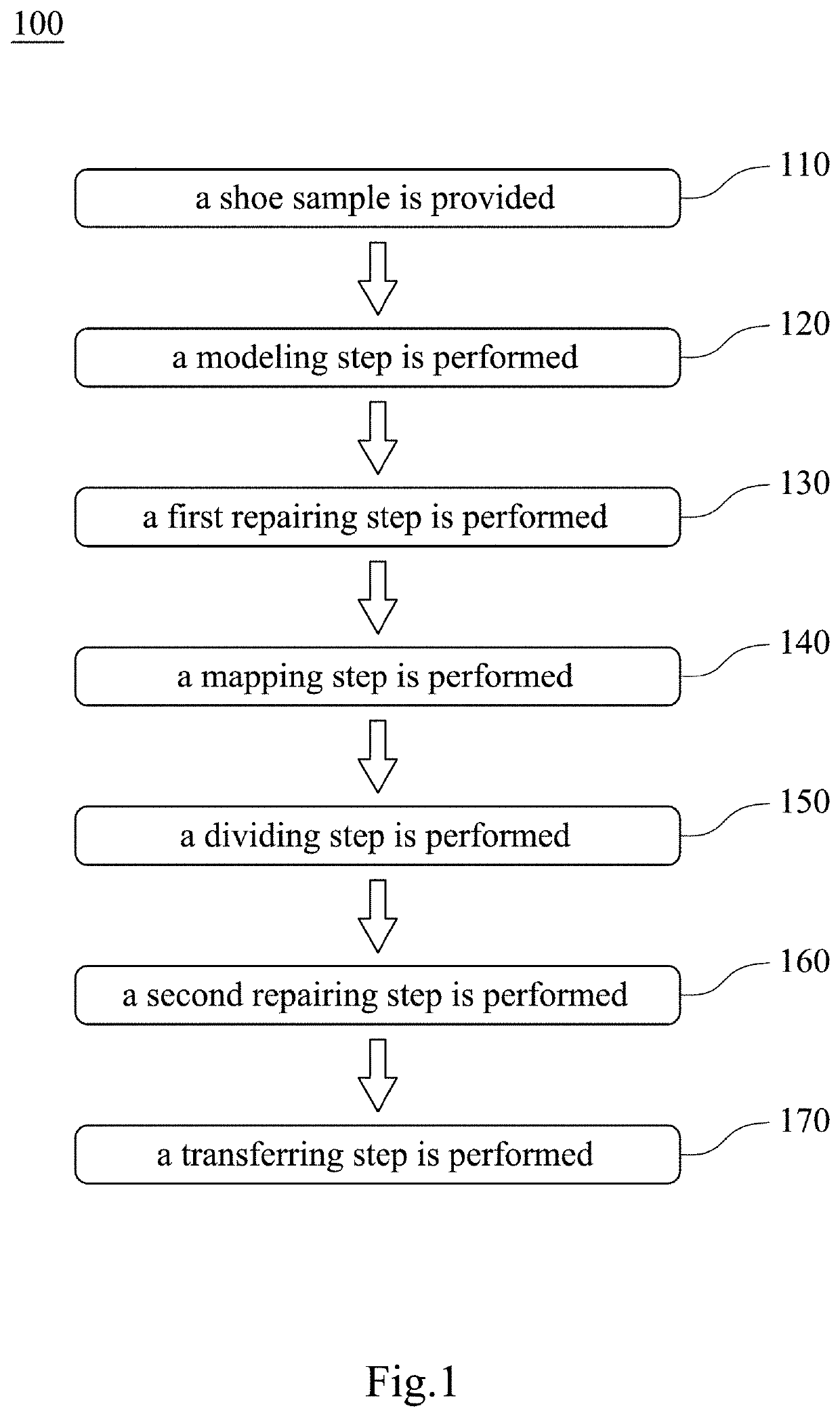
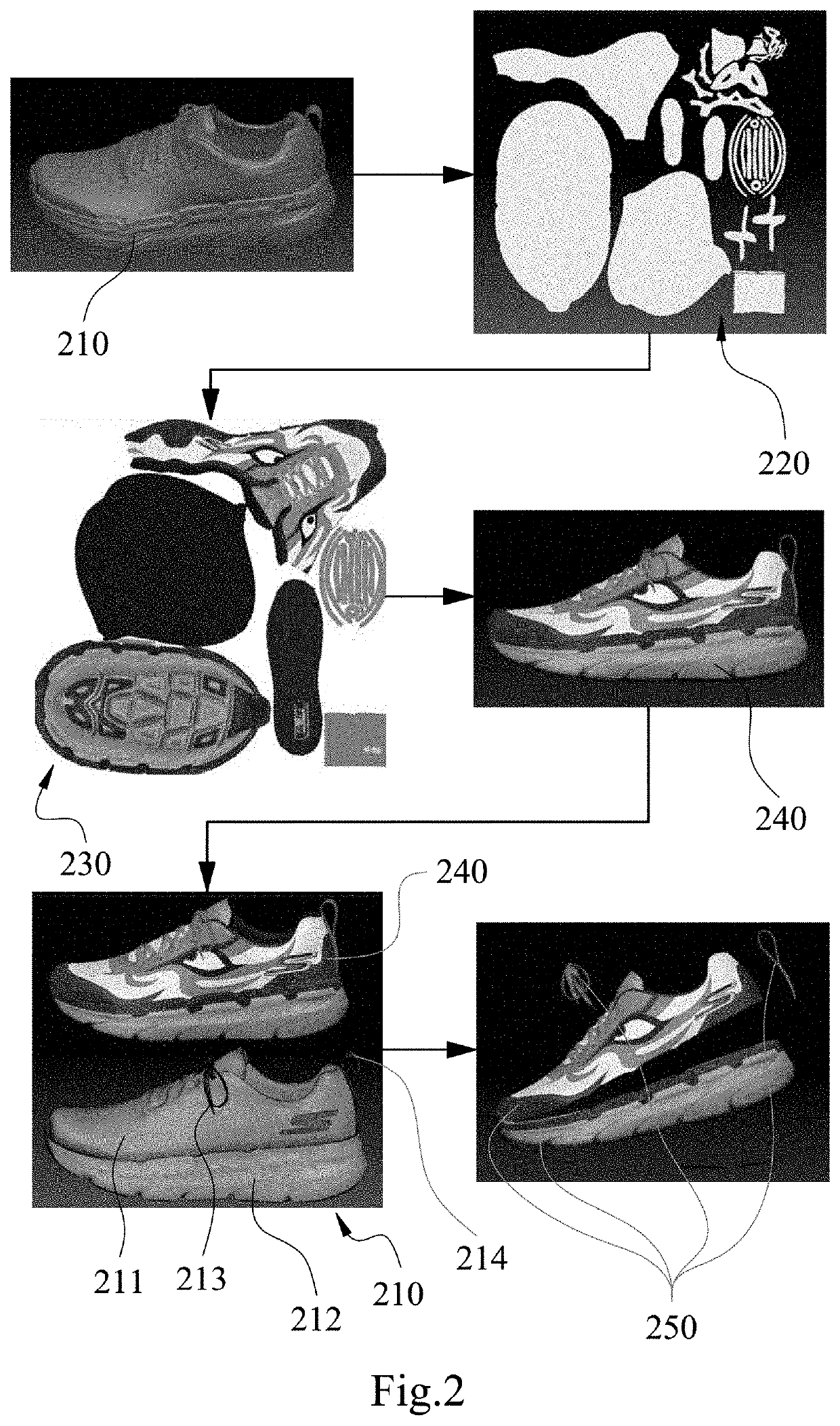
[0018]Please refer to FIG. 1 and FIG. 2. FIG. 1 is a flow chart of a method of modeling part of shoe 100 according to one aspect of the present disclosure. FIG. 2 is a schematic view of different steps of the method 100 of FIG. 1. The method of modeling part of shoe 100 includes Step 110, Step 120, Step 130, Step 140, Step 150, Step 160 and Step 170.

[0019]In Step 110, a shoe sample is provided. The shoe sample can be a shoe product already for sale or a shoe prototype built during the development of a shoe.

[0020]In St...


PUM

PropertyMeasurementUnit
Fractionaaaaaaaaaa
Structureaaaaaaaaaa
Dynamicaaaaaaaaaa

Abstract

According to one aspect of the present disclosure, a method of modeling part of shoe includes steps as follows. A shoe sample is provided, a modeling step is performed, a mapping step is performed, a dividing step is performed and a transferring step is performed. In the modeling step, the shoe sample is 3D-scanned to establish a structural model. In the mapping step, a plurality of shoe texture photos are shot from the shoe sample, and the plurality of shoe texture photos are mapped to the structural model, so as to form a shoe model with a texture. In the dividing step, the structural model is divided into at least two part prototypes according to the texture of the shoe model. In the transferring step, the texture of the shoe model is transferred to the at least two part prototypes to form at least two part models.

Description

RELATED APPLICATIONS[0001]This application claims priority to Taiwan Application Serial Number 109124999, filed Jul. 23, 2020, which is herein incorporated by reference.BACKGROUNDTechnical Field[0002]The present disclosure relates to a method of 3D modeling. More particularly, the present disclosure relates to a method of establishing 3D models of parts of a shoe.Description of Related Art[0003]Due to the development of 3D drafting technology, it has gradually changed the design of footwear from drafting 2D technical drawings to creating 3D models by computers. When a shoe is designed by 2D drawings, it was difficult for the designer to imagine the 3D construction of the finished shoe. Therefore, the finished shoe usually falls short of the designer's requirements, which needs repeating building and correcting shoe prototypes to make the finished shoe meet the requirements. Conversely, when a shoe is designed by 3D drafting technique, the designer can predict the construction of the...

Claims


Application Information

Patent Timeline
IPC IPC(8): G06F30/12G06F30/20G06T15/04G06T17/00G06T19/20G06T19/00B29C64/393B33Y50/02
CPCG06F30/12G06F30/20G06T15/04B33Y50/02G06T19/20G06T19/006B29C64/393G06T17/00B33Y80/00A43D2200/60A43B3/0078G06F2113/10G06F30/17
Inventor SHIAO, JUI-FEN
Owner DAH LIH PUH
Learn More