Method for the application of a tubular hull to an electric cable

a technology of tubular hulls and electric cables, which is applied in the direction of rigid-tube cables, cable installation apparatus, electrical equipment, etc., can solve the problems of significant radial contraction of electric tethers, plastic deformation of electric conductors being provided, and significant elongation of original length of electric tethers

Pending Publication Date: 2022-01-27
SWISS INVENTIX GMBH
View PDF0 Cites 2 Cited by
  • Summary
  • Abstract
  • Description
  • Claims
  • Application Information

AI Technical Summary

Benefits of technology

[0008]It is an object of the present invention to provide an efficient method for the application of a tubular hull comprising a plurality of ring-shaped elements and / or of tube-shaped elements to an electric cable.

Problems solved by technology

As a result, the electric tether can show a significant elongation of its original length under high load conditions.
As a consequence, the mechanical stress caused by winding up the electric tether onto a drum can also lead to plastic deformation of the electric conductors being provided within the electric tether.
An axial tension of an electric tether and external mechanical stress does not only lead to an elongation of the tether along of its longitudinal direction, but can also lead to significant radial contraction of the electric tether at the same time.
As a result, radial compression forces can occur which act on the inner parts of the tether and can easily lead to plastic deformation and overall failure of the electric tether.
The efficient application of a tubular hull made of such ring-shaped compression resistant elements to an electric cable remains, however, a yet unsolved problem in the state-of-the-art.

Method used


Image

  • Method for the application of a tubular hull to an electric cable
  • Method for the application of a tubular hull to an electric cable
  • Method for the application of a tubular hull to an electric cable

Examples


Embodiment Construction

[0068]FIG. 1—Overview of the Tubular Hull Application Device

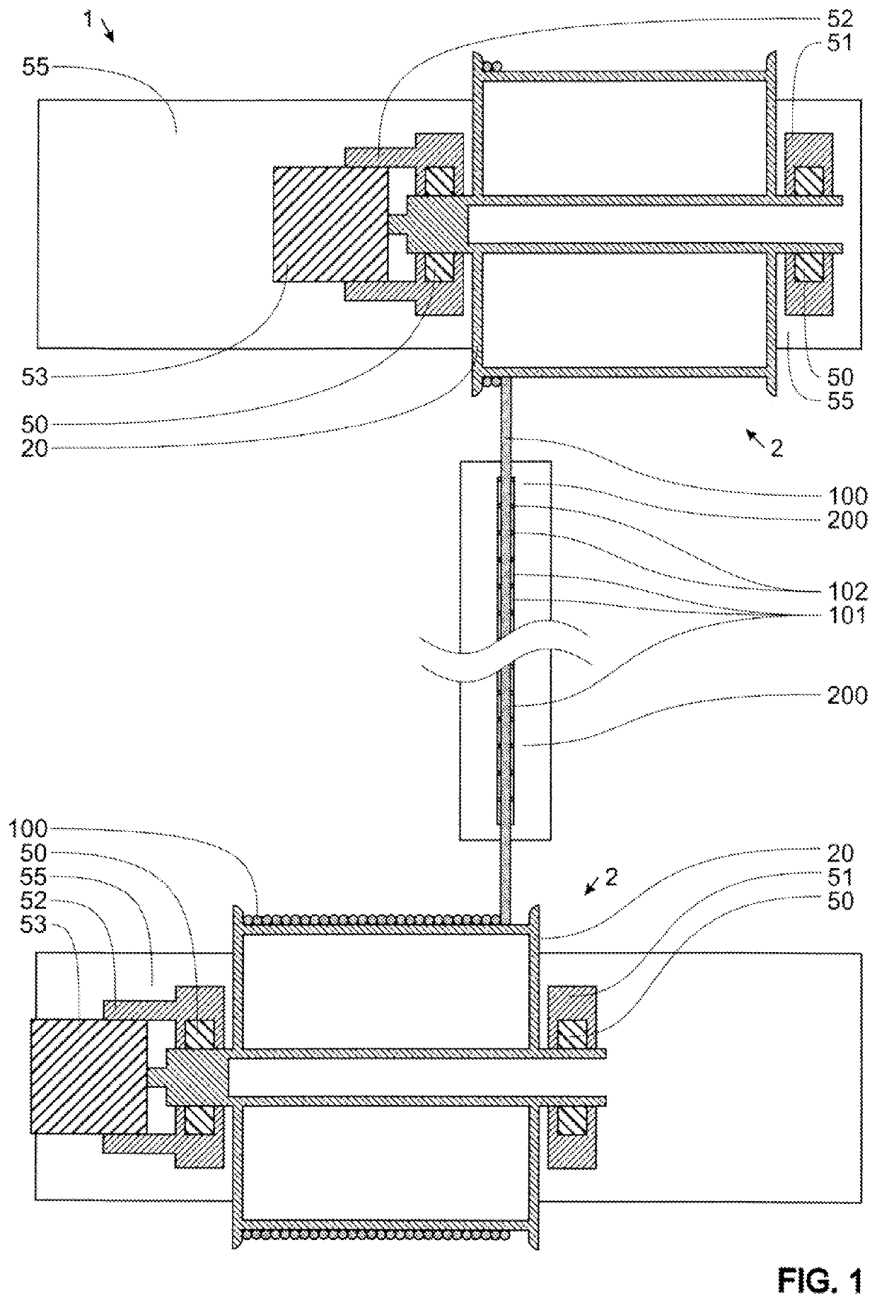
[0069]FIG. 1 shows a schematic overview of a tubular hull application device 1 for the application of stiff tubes 101 and flexible rings 102 to an electric cable 100.

[0070]The electric cable 100 is spooled from a first linearly moveable drum unit 2 to a second linearly moveable drum unit 2 by passing a tubular hull application unit 200. At the tubular hull application unit 200, stiff tubes 101 and flexible rings 102 are supplied for the application to the electric cable 100. Each of the linearly moveable drum units 2 contains a drum 20 for spooling and unspooling the electric cable 100. Each of the drums 20 is driven by a linearly moveable drum unit drive 53. The linearly moveable drum unit drives 53 are held by a linearly moveable drum unit bearing and drive block 52 in each case. The drums 20 run on two linearly moveable drum unit bearings 50 which are fixed in a linearly moveable drum unit bearing block 51 and in the lin...


PUM

PropertyMeasurementUnit
voltagesaaaaaaaaaa
voltagesaaaaaaaaaa
voltagesaaaaaaaaaa

Abstract

A method for the application of a tubular hull (120) to an electric cable (100) is provided. The tubular hull (120) comprises a plurality of ring-shaped elements (102) and / or of tube-shaped elements (101). The method comprises at least the following steps: a.) pre-arranging a part of the tubular hull (120) by means of a tubular hull application unit (200); b.) inserting the electric cable (100) into the tubular hull application unit (200) and into the pre-arranged part of the tubular hull (120); c.) removing the electric cable (100) from the tubular hull application unit (200); and x.) repeating steps a.), b.) and c.) at least two times and in consecutive order. Furthermore, a tubular hull application unit adapted for carrying out such a method and a tether produced according to this method and comprising an electric cable and a tubular hull are provided.

Description

TECHNICAL FIELD[0001]The present invention concerns a method for the application of a tubular hull to an electric cable as well as a tubular hull application unit adapted for carrying out such a method.PRIOR ART[0002]In many applications, electric tethers are used which are not only suited for the transmission of electric power and / or data signals, but which are also adapted to resist axial and radial mechanical loads at least to a certain degree. Data signals can be all sorts of electrically transmittable signals, such as control signals, steering signals, sensor signals and so on.[0003]A technical field in which electric tethers are used that have to absorb substantial axial and radial mechanical loads is for example the field of airborne wind power stations. Airborne wind power stations comprise one or more electric generators mounted on a flying object which usually has an airplane-like construction. The propeller equipped generators are driven by wind and by special flight mano...

Claims


Application Information

Patent Timeline
Patent Type & Authority Applications(United States)
IPC IPC(8): H02G3/04H02G1/14H01B13/004
CPCH02G3/0481H01B13/004H02G1/14H02G1/00H02G3/0462
Inventor NEUHOLD, STEFAN
Owner SWISS INVENTIX GMBH
Why Eureka
Try Eureka