
Vehicle transmission system and method for operation of the transmission system

a transmission system and vehicle technology, applied in the direction of electric propulsion mounting, vehicle sub-unit features, gearing, etc., can solve the problems of premature degradation of transmission components, reduced vehicle performance, and reduced vehicle drivability, so as to reduce vehicle drivability, increase performance, and reduce vehicle performance

Active Publication Date: 2022-02-03
DANA HEAVY VEHICLE SYSTEMS GROUP LLC
View PDF0 Cites 0 Cited by
  • Summary
  • Abstract
  • Description
  • Claims
  • Application Information

AI Technical Summary

Benefits of technology

This patent is about a transmission system for electric vehicles that uses multiple gear ratios for smoother shifting and increased efficiency. The system includes a set of planetary gear sets and brakes that can be selectively engaged or disengaged using a lock-up clutch and brakes. The system also allows for a smooth transition between different gear ratios, reducing noise and vibration for improved driving experience. The use of brakes in the system is minimized, reducing costs and complexity. Overall, this transmission system improves performance, efficiency, and driving experience for electric vehicles.

Problems solved by technology

When a transmission exhibits a power interruption during shifting, vehicle performance is decreased and vehicle drivability is diminished due to driver perceived noise, vibration, and harshness (NVH).
The NVH may in certain scenarios cause premature degradation of transmission components.
However, friction clutches may be relatively large in size and high in cost.
Transmission inefficiencies may stem from the extended use of the transmission brakes.
The brakes generate waste heat that may decrease brake efficiency and flow to brake actuators such as solenoids or hydraulic pumps, in some cases.
Brake actuator performance may diminish due to the elevated actuator temperatures.
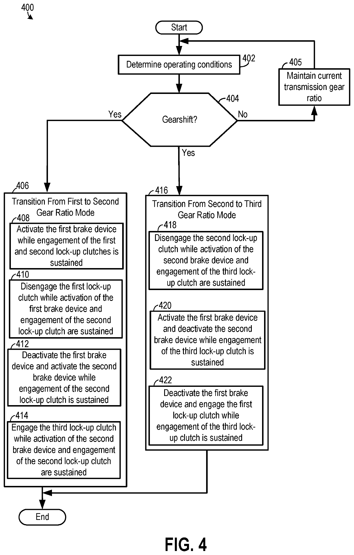
In this way, the transmission system may smoothly transition between the first and second gear ratios, if wanted, resulting in increased transmission efficiency and decreased NVH.

Method used


Image

  • Vehicle transmission system and method for operation of the transmission system
  • Vehicle transmission system and method for operation of the transmission system
  • Vehicle transmission system and method for operation of the transmission system

Examples


Embodiment Construction

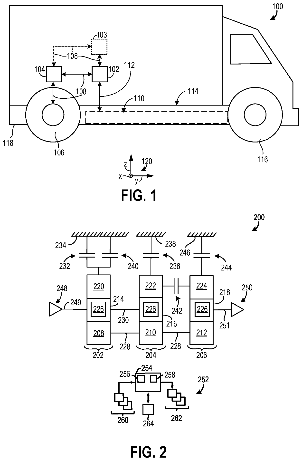
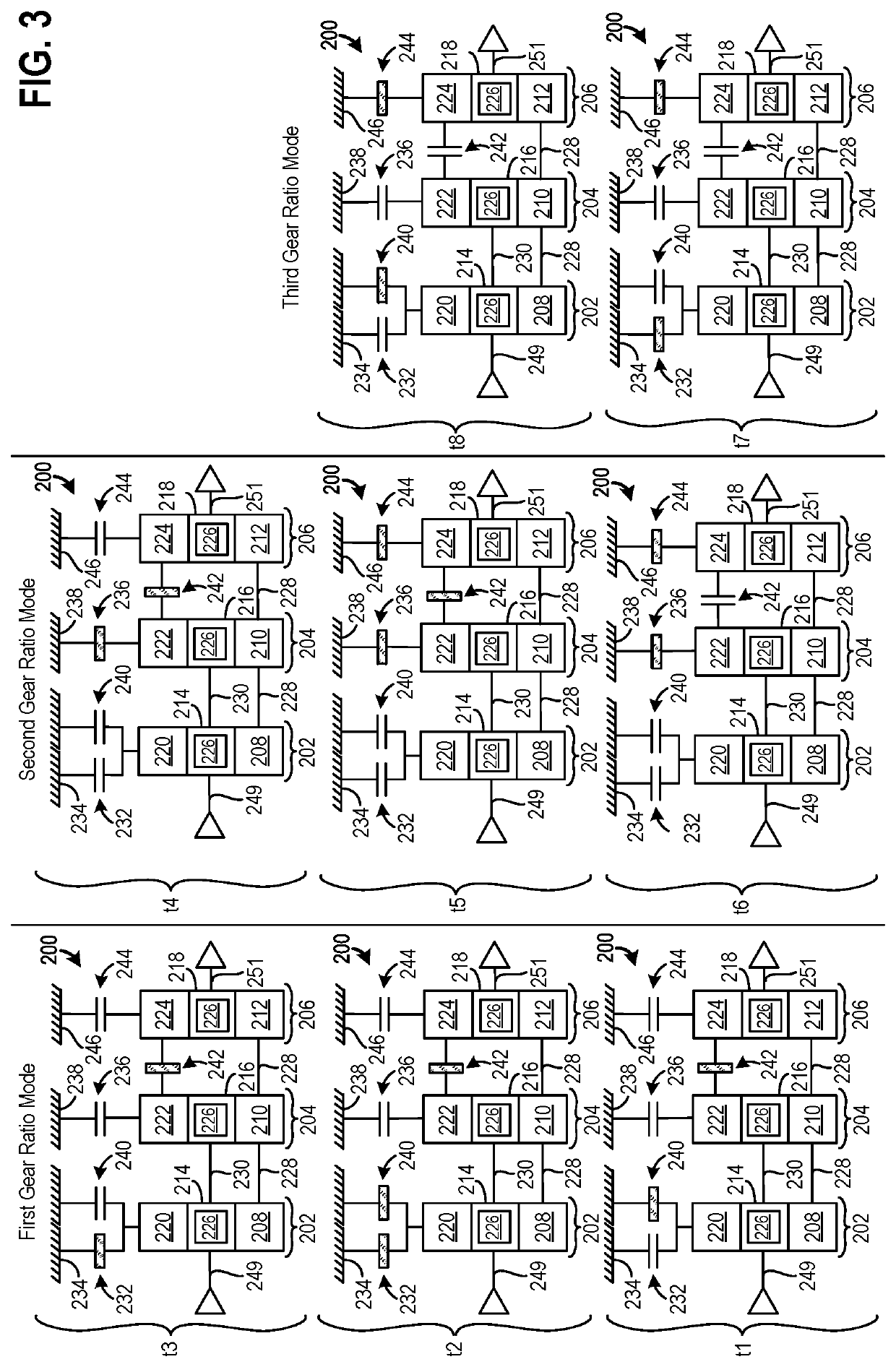
[0015]A transmission system in vehicle achieving a space efficient arrangement with at least three selectable gear ratios, is described herein. The transmission system includes three planetary gear sets with a first brake device and a first lock-up clutch coupled in parallel to a ring gear in a first planetary gear set. Using the brake device and lock-up clutch arranged in parallel in the system makes possible an increase in system space efficiency, in comparison to transmissions using bulkier friction clutches. Brake devices and lock-up clutches may be less costly than friction clutches, in certain cases. The system's manufacturing costs may therefore be reduced. The first lock-up clutch is designed to ground the ring gear to a fixed component during a first gear ratio mode.

[0016]Coordinated operation of the first brake device and lock-up clutch allows smoother shifts between active gear ratios to transpire, such as a shift between the first and second gear ratios. Put another way,...


PUM


Abstract

Methods and systems for a vehicle are provided. A transmission system includes, in one example, a first planetary gear set including a first ring gear and a first sun gear, a second planetary gear set that includes a second ring gear and a second sun gear, and a third planetary gear set that includes a third ring gear and a third sun gear. The transmission system further includes a first brake device configured to selectively ground the first ring gear, a second brake device configured to selectively ground the second ring gear, and a first lock-up clutch configured to selectively ground the first ring gear, wherein the first sun gear, the second sun gear, and the third sun gear are coupled in series.

Description

CROSS REFERENCE TO RELATED APPLICATION[0001]The present application claims priority to U.S. Provisional Patent Application No. 63 / 059,049, entitled “VEHICLE TRANSMISSION SYSTEM AND METHOD FOR OPERATION OF THE TRANSMISSION SYSTEM,” and filed on Jul. 30, 2020. The entire contents of the above-listed application are hereby incorporated by reference for all purposes.TECHNICAL FIELD[0002]The present disclosure relates to a vehicle transmission system, and more particularly to a multi-speed transmission system and method for operation of said system.BACKGROUND AND SUMMARY[0003]Electric vehicles use multi-speed transmissions with discrete gear ratios. Some transmissions deploy planetary gear sets coupled to one another to achieve multiple selectable gears in a compact arrangement. When a transmission exhibits a power interruption during shifting, vehicle performance is decreased and vehicle drivability is diminished due to driver perceived noise, vibration, and harshness (NVH). The NVH may...

Claims


Application Information

Patent Timeline
IPC IPC(8): F16H3/66B60K17/04B60K1/00
CPCF16H3/66B60K17/046F16H2200/2043F16H2200/201B60K1/00F16H3/64F16H61/04F16H2061/0455F16H2200/0021F16H2200/0039F16H2200/2094B60Y2200/91B60K17/02B60K17/08B60Y2400/73F16H3/62
Inventor BEAUDOIN, MARC-ANTOINE
Owner DANA HEAVY VEHICLE SYSTEMS GROUP LLC
Learn More