Fuel shift monitor

a technology of shift monitor and fuel shift, which is applied in the direction of electric control, combustion engines, machines/engines, etc., can solve the problems of increasing emissions and/or reducing vehicle drivability, and achieve the effects of reducing vehicle drivability, reducing engine control degradation probability, and increasing emissions

Active Publication Date: 2016-09-20
FORD GLOBAL TECH LLC
View PDF7 Cites 1 Cited by
  • Summary
  • Abstract
  • Description
  • Claims
  • Application Information

AI Technical Summary

Benefits of technology

[0003]The air-fuel ratio of exhaust gases may fluctuate from a desired ratio due to degradation in one or more components (e.g., a mass air flow (MAF) sensor, a fuel pump, etc.) or a change in fuel type. A lean fuel shift may result in a leaner than desired air-fuel ratio while a rich fuel shift may cause a richer than desired air-fuel ratio. Fuel shifts may affect engine control leading to an increase in emissions and / or reduced vehicle drivability. Accordingly, accurate determination of existing fuel shifts may reduce the likelihood of engine control degradation.
[0004]The inventors herein have recognized the above issues and identified an approach to at least partly address the above issues. In one embodiment, a method for an engine is provided for indicating a fuel shift based on a time delay of an exhaust gas sensor during an entry into and an exit out of deceleration fuel shut off (DFSO). Herein, fuel shifts during engine operation may be detected more accurately in a manner using existing hardware and fuel modulations that occur during DFSO events.
[0006]In this way, a non-intrusive and passive approach may be used to detect the presence of fuel shifts. Time delay responses from the exhaust gas sensor during entry into and exit out of DFSO events may provide a more robust signal that has less noise and higher fidelity. Thus, a more reliable diagnosis of existing fuel shifts may be made. Further, these fuel shifts may be mitigated by using closed loop feedback control and by tailoring engine control (e.g., throttle position, fuel injection amount and / or timing) responsive to the type of fuel shift.

Problems solved by technology

Fuel shifts may affect engine control leading to an increase in emissions and / or reduced vehicle drivability.

Method used


Image

  • Fuel shift monitor
  • Fuel shift monitor
  • Fuel shift monitor

Examples


Embodiment Construction

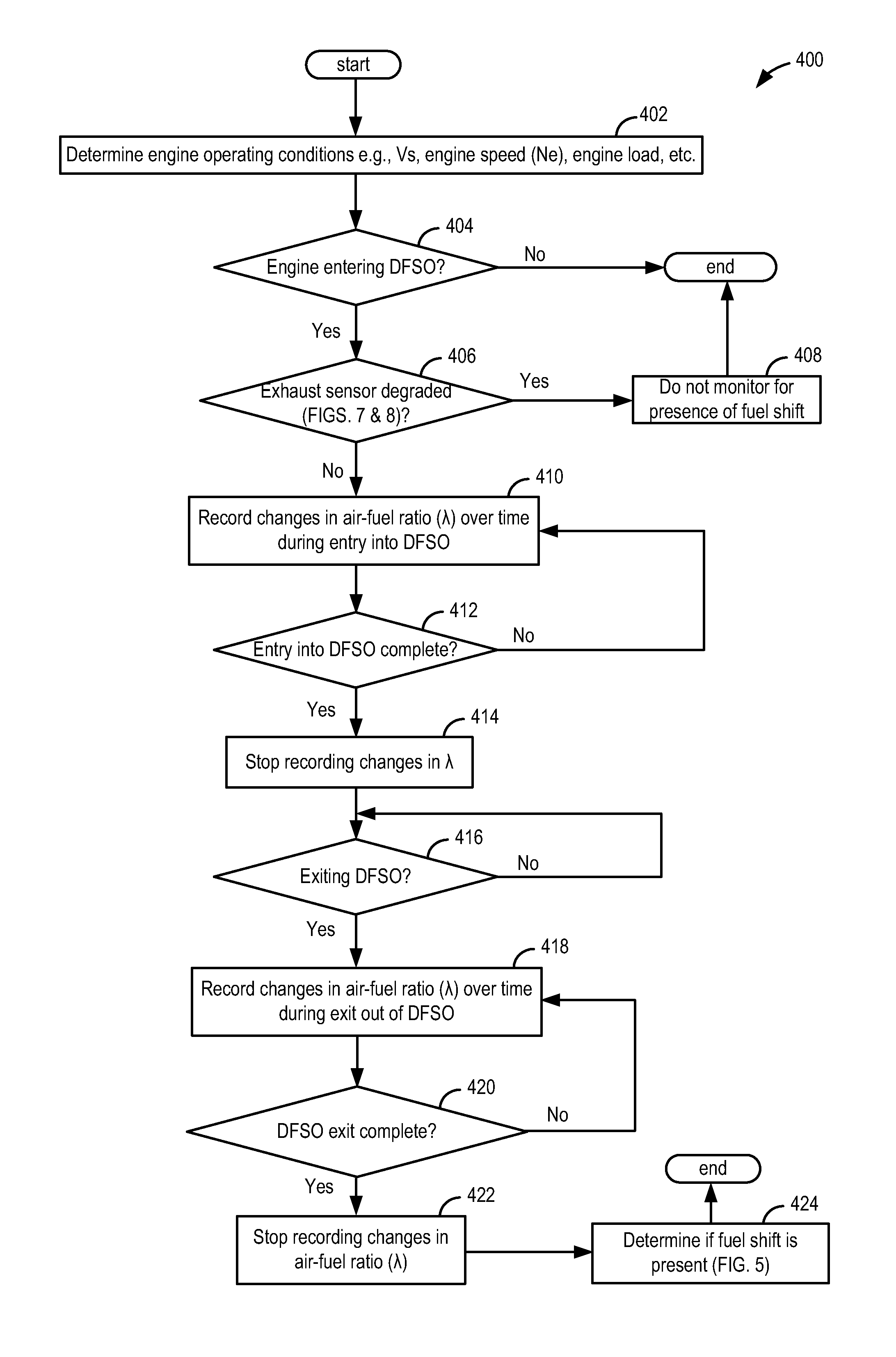
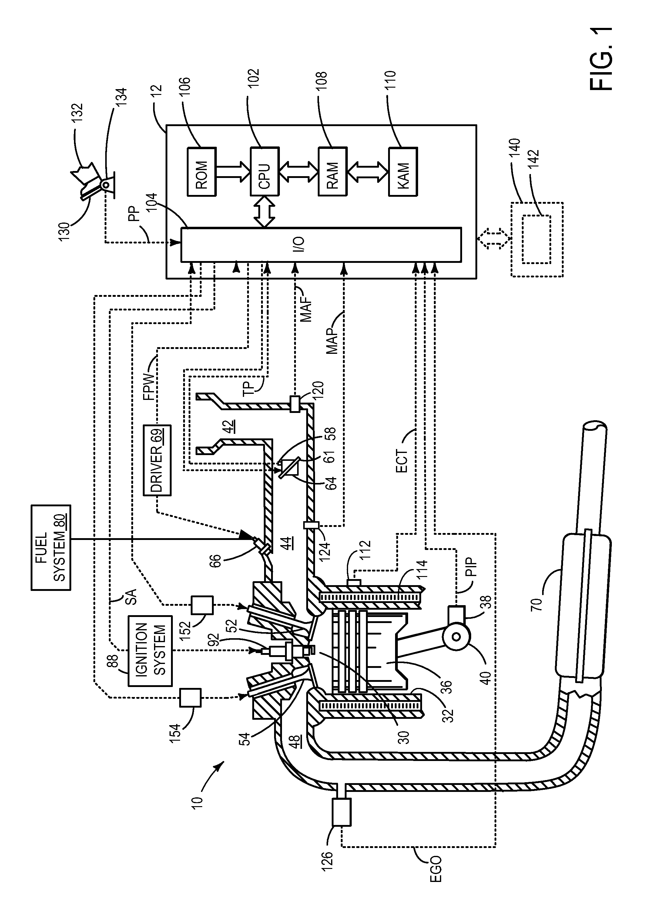
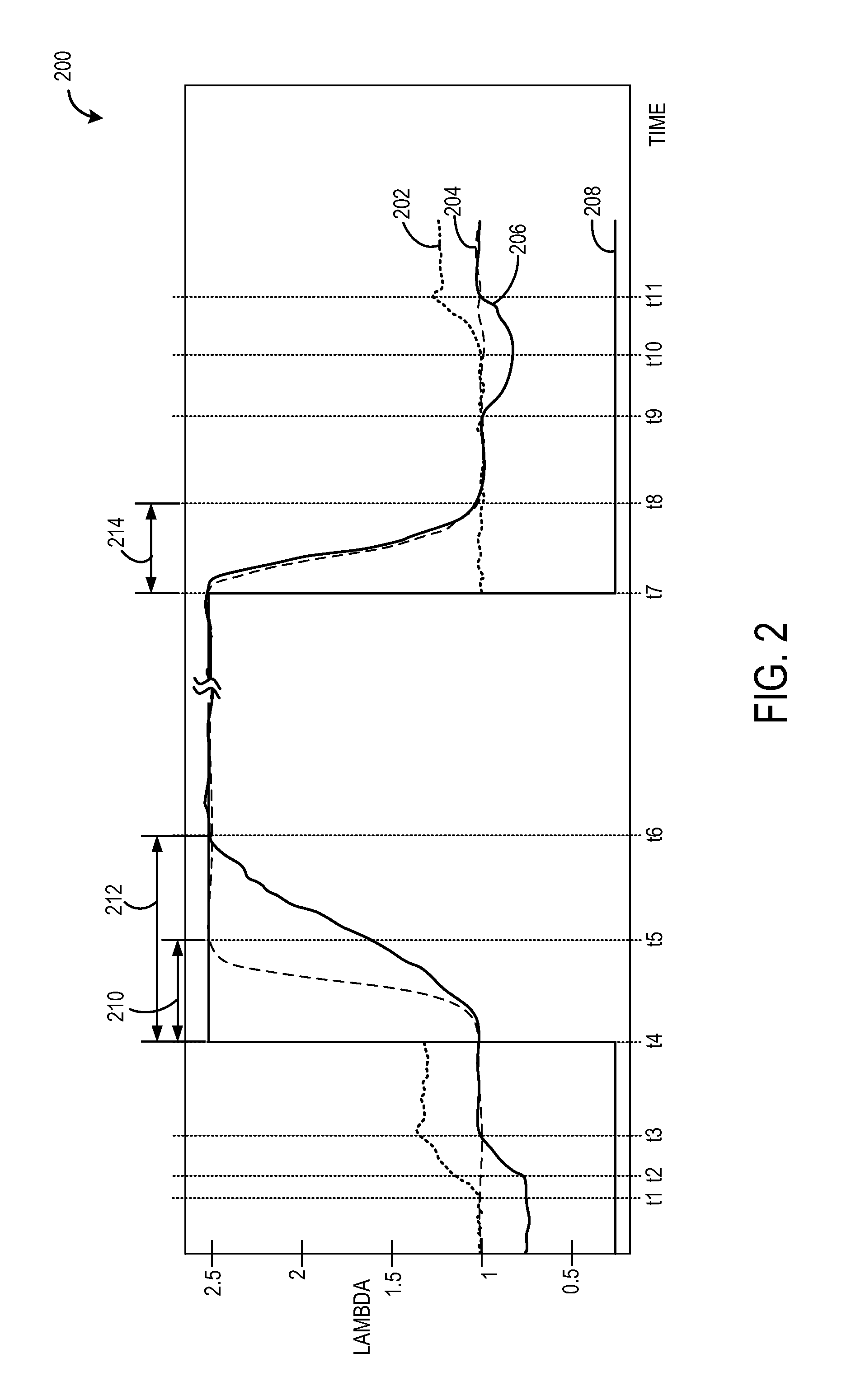
[0017]The following description relates to an approach for determining the presence of fuel shifts in an engine system, such as the engine system of FIG. 1. A fuel shift may be determined via monitoring time delay responses from an exhaust gas sensor during each entry into and exit out of DFSO, as shown in FIGS. 2 and 3, to non-intrusively monitor exhaust gas sensor responses during rich-to-lean and lean-to-rich transitions. Prior to monitoring time delays, the exhaust gas sensor may be evaluated for degradation based on six types of degradation behavior (FIGS. 7a-7f) and based on characteristics of a distribution of extreme values of calculated air-fuel ratio (also termed lambda) differentials (FIGS. 8a-8b). A controller may be configured to perform routines, such as those shown in FIGS. 4-6, for determining the presence of a fuel shift, classifying the fuel shift as a rich fuel shift or a lean fuel shift, and for adjusting engine operating parameters based on the determined fuel s...


PUM


Abstract

Methods and systems are described for evaluating presence of fuel shifts in an engine. In one example, a method comprises indicating a fuel shift based on a time delay of an exhaust gas sensor during an entry into and an exit out of deceleration fuel shut off (DFSO).

Description

TECHNICAL FIELD[0001]The present disclosure relates to detecting fuel shifts in a motor vehicle.BACKGROUND AND SUMMARY[0002]An exhaust gas sensor may be positioned in an exhaust system of a vehicle to detect an air-fuel ratio of exhaust gas exiting from an internal combustion engine of the vehicle. Exhaust gas sensor readings may be used to control operation of the internal combustion engine to propel the vehicle.[0003]The air-fuel ratio of exhaust gases may fluctuate from a desired ratio due to degradation in one or more components (e.g., a mass air flow (MAF) sensor, a fuel pump, etc.) or a change in fuel type. A lean fuel shift may result in a leaner than desired air-fuel ratio while a rich fuel shift may cause a richer than desired air-fuel ratio. Fuel shifts may affect engine control leading to an increase in emissions and / or reduced vehicle drivability. Accordingly, accurate determination of existing fuel shifts may reduce the likelihood of engine control degradation.[0004]The...

Claims


Application Information

Patent Timeline
Patent Type & Authority Patents(United States)
IPC IPC(8): F02D41/14F02D41/22F02D41/12F02D41/24
CPCF02D41/1454F02D41/123F02D41/1402F02D41/1439F02D41/1495F02D41/222F02D41/2441F02D41/2454F02D41/126F02D41/1456F02D2041/224Y02T10/40
Inventor JAMMOUSSI, HASSENEMAKKI, IMAD HASSANUHRICH, MICHAEL JAMESCASEDY, MICHAELBEHR, KENNETH JOHN
Owner FORD GLOBAL TECH LLC
Why Eureka
Try Eureka