Method and system for providing boost to an internal combustion engine

Active Publication Date: 2019-08-22
FORD GLOBAL TECH LLC
View PDF3 Cites 0 Cited by
  • Summary
  • Abstract
  • Description
  • Claims
  • Application Information

AI Technical Summary

Benefits of technology

[0003]During the course of everyday driving, driving conditions may change such that a human driver may request a larger driver demand torque or increased vehicle acceleration in response to the change in driving conditions. However, the human driver may provide a delayed response to the change in driving conditions so that the human driver falls behind traffic conditions and then attempts to catchup to the change in traffic conditions by increasing driver demand torque or requested vehicle acceleration. Nevertheless, the vehicle may not respond as quickly as the human driver would like, so the human driver may increase the driver demand torque or requested vehicle acceleration amount even more. Consequently, the vehicle may eventually accelerate at a rate that is faster than if the human driver had provided a timely more subdued response to the changing traffic conditions. As a result, vehicle fuel consumption and emissions may increase. Further, vehicle drivability and comfort may decrease.
[0004]The inventors herein have recognized the above-mentioned issues and have developed a vehicle operating method, comprising: receiving road condition data to a controller; increase a boost amount a predetermined boost amount in response to the road condition data via the controller; and adjusting the predetermined boost amount in response to a difference between an actual boost amount and a desired boost amount, where the actual boost amount is generated via increasing the boost amount by the predetermined boost amount. Specifically, the method exploits a delay in human driver response to external stimulus. For non-emergency actions/maneuvers, human drivers ex

Problems solved by technology

Turbochargers may increase boost as engine speed and load increase, but turbochargers may not increase boost as fast as is desired, especially at low engine speeds, because of inertia of turbocharger components and because of limited energy in the engine exhaust during some conditions.
Supercharger response may also be delayed if the supercharger is clutch operated.
Accordingly, if a human driver applies an accelerator pedal or directly requests vehicle acceleration, the engine and vehicle may not respond as quickly as is desired by the human driver.
However, the human dr

Method used


Image

  • Method and system for providing boost to an internal combustion engine
  • Method and system for providing boost to an internal combustion engine
  • Method and system for providing boost to an internal combustion engine

Examples


Example

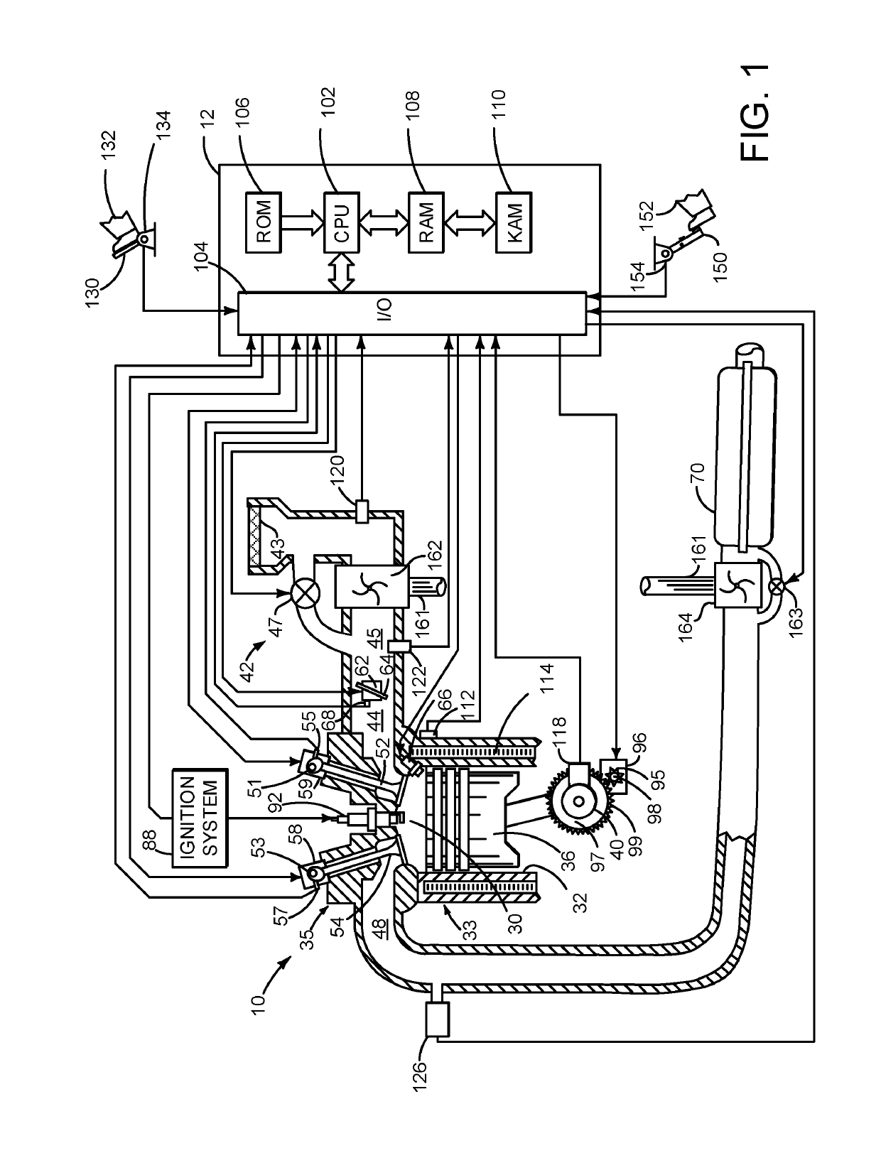
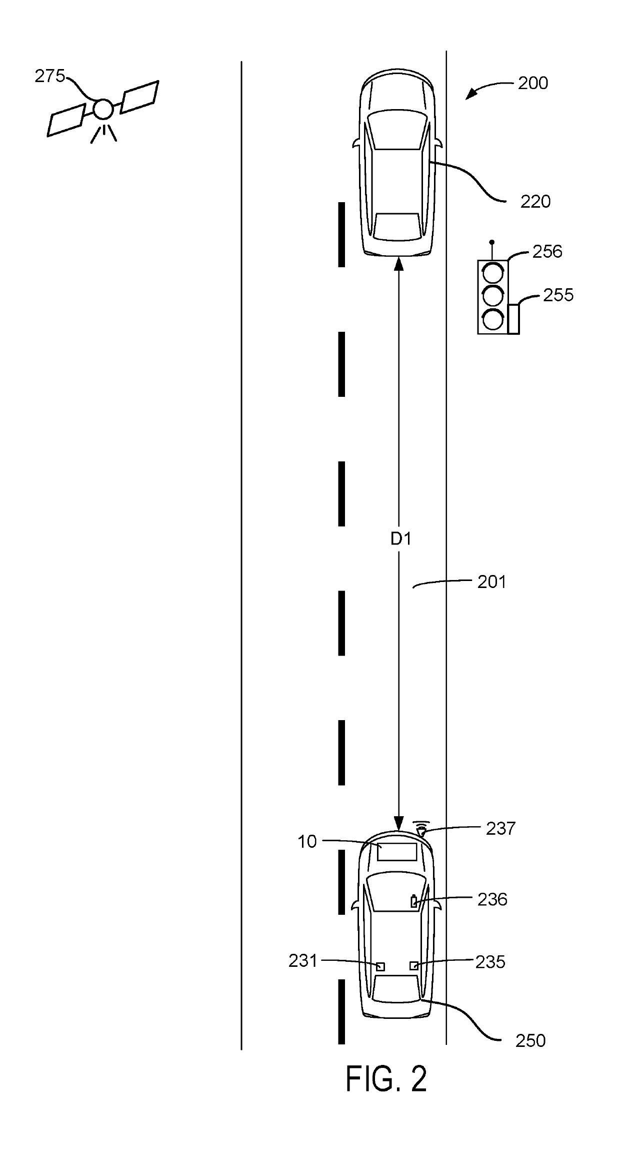
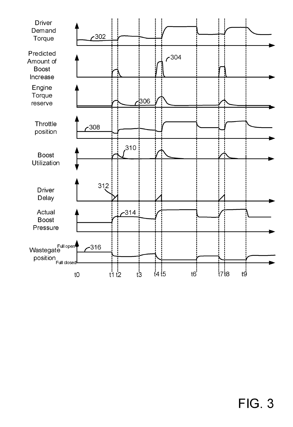
[0014]The present description is related to generating boost within an internal combustion engine. Boost is generated before it is demanded so that engine torque production lag may be reduced. In one example, boost may be increased in response to road conditions that may provide impetus to a human driver to increase a driver demand torque or a vehicle acceleration request. The boost may be generated in an engine as is shown in FIG. 1. The engine of FIG. 1 may be included in a vehicle as is shown in FIG. 2. The engine and vehicle may operate as is shown in the sequence of FIG. 3. Driver demand delay relative to a change in road conditions and the evolution of boost pressures in an engine are shown in the plot of FIG. 4. A flowchart of a method for generating boost within an engine is shown in FIG. 5.

[0015]Referring to FIG. 1, internal combustion engine 10, comprising a plurality of cylinders, one cylinder of which is shown in FIG. 1, is controlled by electronic engine controller 12. ...


PUM


Abstract

A method for adjusting boost provided via a turbocharger or supercharger is described. In one example, boost is increased in response to a change in road conditions before a driver reacts to the change in road conditions by applying an accelerator pedal. The boost is increased to reduce compressor lag, thereby increasing the responsiveness of the engine and vehicle.

Description

FIELD[0001]The present description relates to methods and a system for providing boost to an internal combustion engine of a vehicle. The boost may be provided via a turbocharger or a supercharger and the boost may be provided such that it is provided in anticipation of an increase in driver demand torque or requested vehicle acceleration.BACKGROUND AND SUMMARY[0002]An internal combustion engine may be turbocharged or supercharged to provide pressurized air (e.g., boost) to the engine so that the engine's power output capacity may be increased beyond the engine's power output capacity if the engine were normally aspirated. Turbochargers may increase boost as engine speed and load increase, but turbochargers may not increase boost as fast as is desired, especially at low engine speeds, because of inertia of turbocharger components and because of limited energy in the engine exhaust during some conditions. Supercharger response may also be delayed if the supercharger is clutch operate...

Claims


Application Information

Patent Timeline
IPC IPC(8): F02D41/00F02D41/24F02B37/18B60W50/00
CPCF02D41/0007F02D41/2451F02B37/18B60W50/0097F02D2200/702F02D2200/602B60W2420/42B60W2420/52F02D2200/501B60W2550/22B60W2550/14B60W2540/10B60W2550/308B60W2550/302F02B37/183F02D29/02F02D2200/70F02D2200/0406Y02T10/12B60W2552/00B60W2554/801B60W2554/804B60W2555/60
Inventor HELLSTROM, JOHN ERIK MIKAELJANKOVIC, MRDJANSANTILLO, MARIO
Owner FORD GLOBAL TECH LLC
Why Eureka
Try Eureka