
Fluidic ejection device with optical blockage detector

a technology of optical blockage detector and ejection device, which is applied in the field of fluidic, can solve the problems of blocked fluid, degraded or missing text or images, and accumulation of blocked fluid, such as ink, so as to reduce the degradation of printed text or images, and avoid fluid ejection errors

Active Publication Date: 2022-02-10
STMICROELECTRONICS (RES & DEV) LTD
View PDF3 Cites 1 Cited by
  • Summary
  • Abstract
  • Description
  • Claims
  • Application Information

AI Technical Summary

Benefits of technology

The optical blockage detector can detect when there is a blockage in the fluidic ejection device. Based on this detection, the device can adjust its operation to avoid errors and improve printing quality. This can prevent degraded text or images and reduce the risk of malfunctioning nozzles.

Problems solved by technology

Unfortunately, it is common for these nozzles to become blocked or clogged with fluid when stored for long periods of time or even during operation of the fluidic device.
For printing applications, for example, blockage of the nozzles often results in text or images with portions being degraded or missing.
In addition, blocked fluid, such as ink, may accumulate over time and eventually protrude from a nozzle.
This may eventually cause all of the nozzles of a fluidic device to malfunction.

Method used


Image

  • Fluidic ejection device with optical blockage detector
  • Fluidic ejection device with optical blockage detector
  • Fluidic ejection device with optical blockage detector

Examples


Embodiment Construction

[0023]In the following description, certain specific details are set forth in order to provide a thorough understanding of various aspects of the disclosed subject matter. However, the disclosed subject matter may be practiced without these specific details. In some instances, well-known structures and methods of manufacturing fluidic devices, light emitting devices, light sensors, integrated circuits, counters, and electrical components (e.g., transistors, resistors, capacitors, etc.) have not been described in detail to avoid obscuring the descriptions of other aspects of the present disclosure.

[0024]Unless the context requires otherwise, throughout the specification and claims that follow, the word “comprise” and variations thereof, such as “comprises” and “comprising,” are to be construed in an open, inclusive sense, that is, as “including, but not limited to.”

[0025]Reference throughout the specification to “one embodiment” or “an embodiment” means that a particular feature, str...


PUM


Abstract

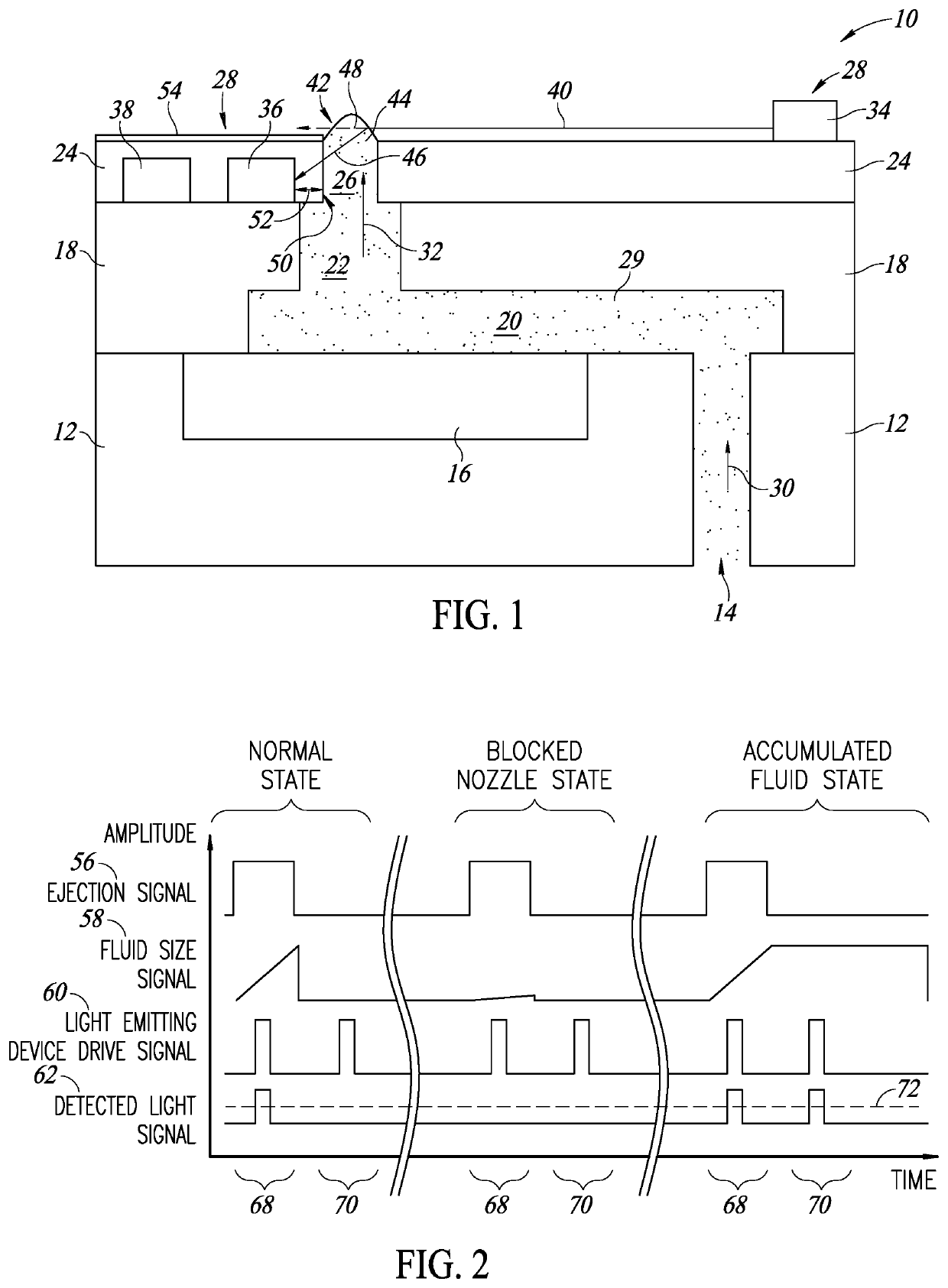
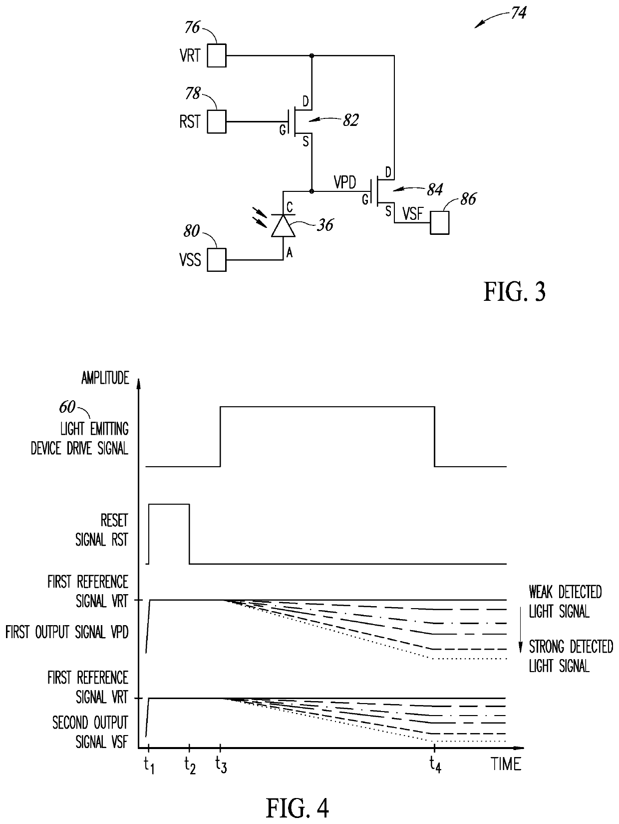
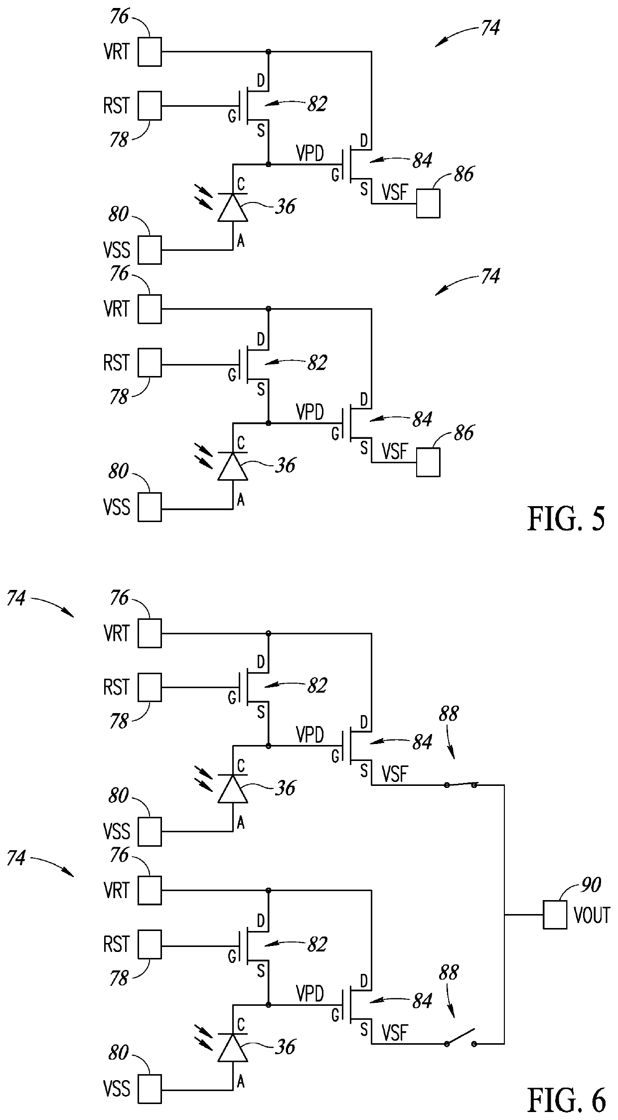
The present disclosure is directed to a fluidic ejection device configured to detect whether one or more nozzles of the fluidic ejection device is in a normal state, a blocked nozzle state, or an accumulated fluid state. The fluidic ejection device includes an optical blockage detector having a light emitting device configured to emit a light signal, and a light sensor configured to detect the light signal. The optical blockage detector detects the normal state, the blocked nozzle state, and the accumulated fluid state based on the detected light signal.

Description

BACKGROUNDTechnical Field[0001]The present disclosure is directed to a fluidic device configured to detect blockage of one or more nozzles.Description of the Related Art[0002]Fluidic devices are used for a variety of applications. For example, fluidic devices are often used in printing applications, such as for implementing printer heads for inkjet printers and 3D printers. Fluidic devices are also often used in medical applications to eject, for example, biological materials and drugs into patients.[0003]Typically, fluidic devices include a plurality of nozzles in which fluid is ejected and dispensed from. Unfortunately, it is common for these nozzles to become blocked or clogged with fluid when stored for long periods of time or even during operation of the fluidic device.[0004]The blockage of the nozzles prevents fluid from being ejected properly from the nozzles. For printing applications, for example, blockage of the nozzles often results in text or images with portions being d...

Claims


Application Information

Patent Timeline
IPC IPC(8): B05B12/00
CPCB05B12/004B41J2/16579B29C64/209B33Y30/00B41J2/2142B33Y50/00B29C64/386
Inventor RAYNOR, JEFFREY M.
Owner STMICROELECTRONICS (RES & DEV) LTD
Learn More