Unlock instant, AI-driven research and patent intelligence for your innovation.

Flow control method and rotary wing unit

Pending Publication Date: 2022-02-10
KAWASAKI HEAVY IND LTD +1
View PDF4 Cites 1 Cited by
  • Summary
  • Abstract
  • Description
  • Claims
  • Application Information

AI Technical Summary

Benefits of technology

The present patent is about a method and device for controlling the flow of air around the blade of a rotary wing. A plasma actuator is placed at the blade and an actuator driving frequency is applied to it to control the flow of air. The method involves determining a characteristic frequency ratio that is a numerical value between the actuator driving frequency and the angle of attack changing frequency. This ratio is then used to set the actuator driving frequency, which is applied to the plasma actuator to control the air flow around the blade. The technical effect of this invention is a more accurate control of the flow of air around a rotary wing blade, which improves the efficiency of the rotary wing's operation.

Problems solved by technology

However, when the pitch angle of the blade increases, air current flowing along the surface of the blade may separate from the blade, and the blade may stall.
However, when an area or a period of time in which the stall occurs increases, the effect obtained by the cyclic pitch mechanism cannot be adequately achieved.

Method used


Image

  • Flow control method and rotary wing unit
  • Flow control method and rotary wing unit
  • Flow control method and rotary wing unit

Examples


Embodiment Construction

[0014]Hereinafter, an embodiment will be described with reference to the drawings.

[0015]Rotary Wing Unit

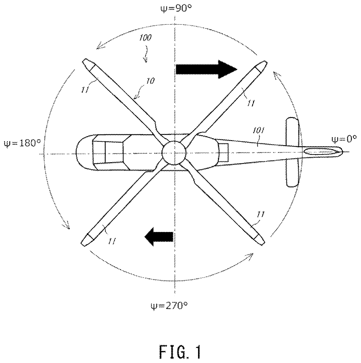
[0016]FIG. 1 is a plan view of a helicopter 101 equipped with a rotary wing unit 100. The rotary wing unit 100 according to the embodiment is mounted on the helicopter 101. Instead of the helicopter, the rotary wing unit 100 may be disposed at other facilities, such as wind power generation facilities. In the embodiment, a left direction on the paper surface of FIG. 1 corresponds to a front direction of the helicopter 101, i.e., a proceeding direction of the helicopter 101. The rotary wing unit 100 includes a rotary wing 10 including blades 11. The rotary wing 10 rotates counterclockwise in plan view.

[0017]The above blades 11 are the same in configuration as each other. Herein, the following will be described while focusing on one of the blades 11. As shown in FIG. 1, a rotation angle (hereinafter referred to as an “azimuth angle ψ”) of the blade 11 when the blade 11 extends from ...


PUM


Abstract

A flow control method is a flow control method of controlling flow around a blade of a rotary wing, a plasma actuator being disposed at the blade. The flow control method includes: determining a characteristic frequency ratio that is a characteristic value among frequency ratios, each of the frequency ratios being a ratio between an actuator driving frequency and an angle of attack changing frequency, the actuator driving frequency being a frequency of an applied voltage applied to the plasma actuator, the angle of attack changing frequency being a frequency at which an angle of attack of the blade changes in accordance with a rotation angle of the blade; setting the actuator driving frequency such that the frequency ratio becomes the characteristic frequency ratio; and applying a voltage of the set actuator driving frequency to the plasma actuator to control the flow around the blade.

Description

CROSS-REFERENCE TO RELATED APPLICATION[0001]This is a Continuation of application Ser. No. 17 / 601,396 filed Oct. 4, 2021, which claims priority to PCT / JP2020 / 015207 filed Apr. 2, 2020, and JP 2019-070570 filed Apr. 2, 2019, both of which are incorporated herein by reference.BACKGROUND OF THE INVENTION1. Field of the Invention[0002]The present disclosure relates to a flow control method and a rotary wing unit, particularly to a method and a rotary wing unit each of which controls flow around a blade of a rotary wing and is capable of easily setting driving of a plasma actuator.2. Description of the Related Art[0003]Helicopters, wind power generation facilities, and the like may include cyclic pitch mechanisms. The cyclic pitch mechanism is a mechanism that periodically changes a pitch angle of a blade constituting a rotary wing. For example, when the blade is at such an angular position that lift is hardly obtained, the cyclic pitch mechanism increases the pitch angle of the blade to...

Claims


Application Information

Patent Timeline
IPC IPC(8): B64C23/04B64C27/04
CPCB64C23/04B64C2230/28B64C2230/12B64C27/04B64C27/72Y02T50/10B64C23/005
Inventor YASUDA, HIDEMASAOCHI, AKIOHAYAMA, KENJITSUJIUCHI, TOMOKANAKAKITA, KAZUYUKINONOMURA, TAKUKOMURO, ATSUSHITAKASHIMA, KEISUKE
Owner KAWASAKI HEAVY IND LTD