Pivot brace type pipe fitting

a pipe fitting and pivoting technology, applied in the direction of couplings, mechanical equipment, etc., can solve the problems of unintentional separation of the pipe, difficult connection of the pipe, and increased external scratches of the pipe b>1/b>, so as to prevent the phenomenon of a pipe falling out, increase stability and reliability, and prevent scratches on the surface of the pip

Inactive Publication Date: 2022-02-10
KIM SUK YOON
View PDF8 Cites 0 Cited by
  • Summary
  • Abstract
  • Description
  • Claims
  • Application Information

AI Technical Summary

Benefits of technology

[0012]A technical task of the present disclosure is to provide a pivot brace type pipe fitting capable of preventing scratches on the surface of a pipe when pipes are connected and controlling the frictional force between the pivot brace and the pipe, thereby preventing a phenomenon of a pipe falling-out and increasing stability and reliability.
[0013]In addition, an aspect of the present disclosure is directed to providing a pivot brace type pipe fitting that is convenient for maintenance and repair since a pipe can be conveniently separated in the case of carrying out maintenance and repair work on a pipe.
[0014]In addition, an aspect of the present disclosure is directed to providing a pivot brace type pipe fitting capable of saving accommodation space of the pivot brace according to the change in bore of the pipe.

Problems solved by technology

Hence, it is difficult to connect the pipe 1, and there is a drawback in that the external scratches of the pipe 1 also become bigger.
Hence, there is a drawback in that the pipe 1 may be unintentionally separated when rotated in the circumferential direction while applying force in the opposite direction when the inserted pipe 1 is coupled.
Hence, it is difficult to insert the pipe 1, and scratches are more commonly generated on the surface of the pipe 1 during an insertion process.
In addition, when the maintenance and repair work of a pipe is performed after the pipe 1 is connected, in order to separate the pipe 1, it is inconvenient to disassemble a pipe connecting device and remove the pivot brace 20.
In addition, there is a drawback in that when the bore of the pipe 1 increases, a space for accommodating the tooth of the pivot brace 20 and a size of the pivot brace 20 that is increased in proportion to the cross-sectional area of the pipe 1 needs to be provided in a connecting device.

Method used


Image

  • Pivot brace type pipe fitting
  • Pivot brace type pipe fitting
  • Pivot brace type pipe fitting

Examples


Embodiment Construction

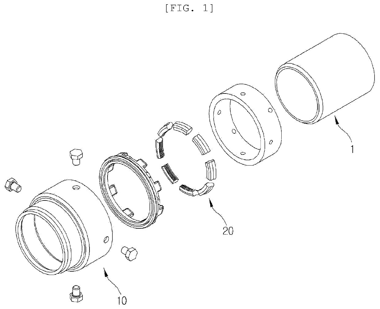
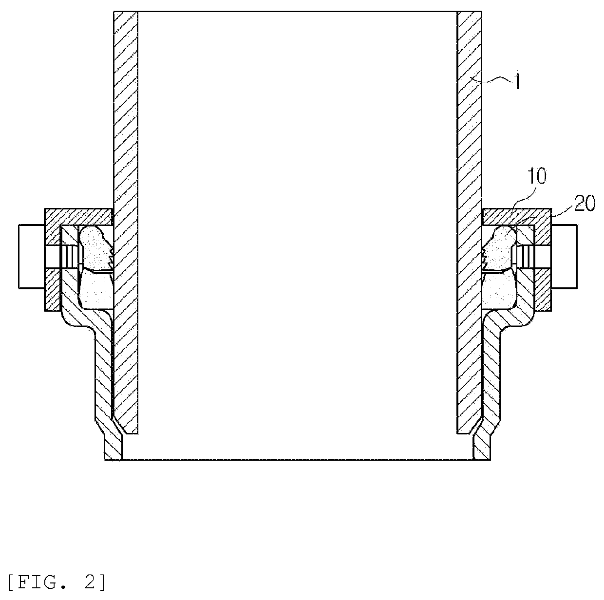
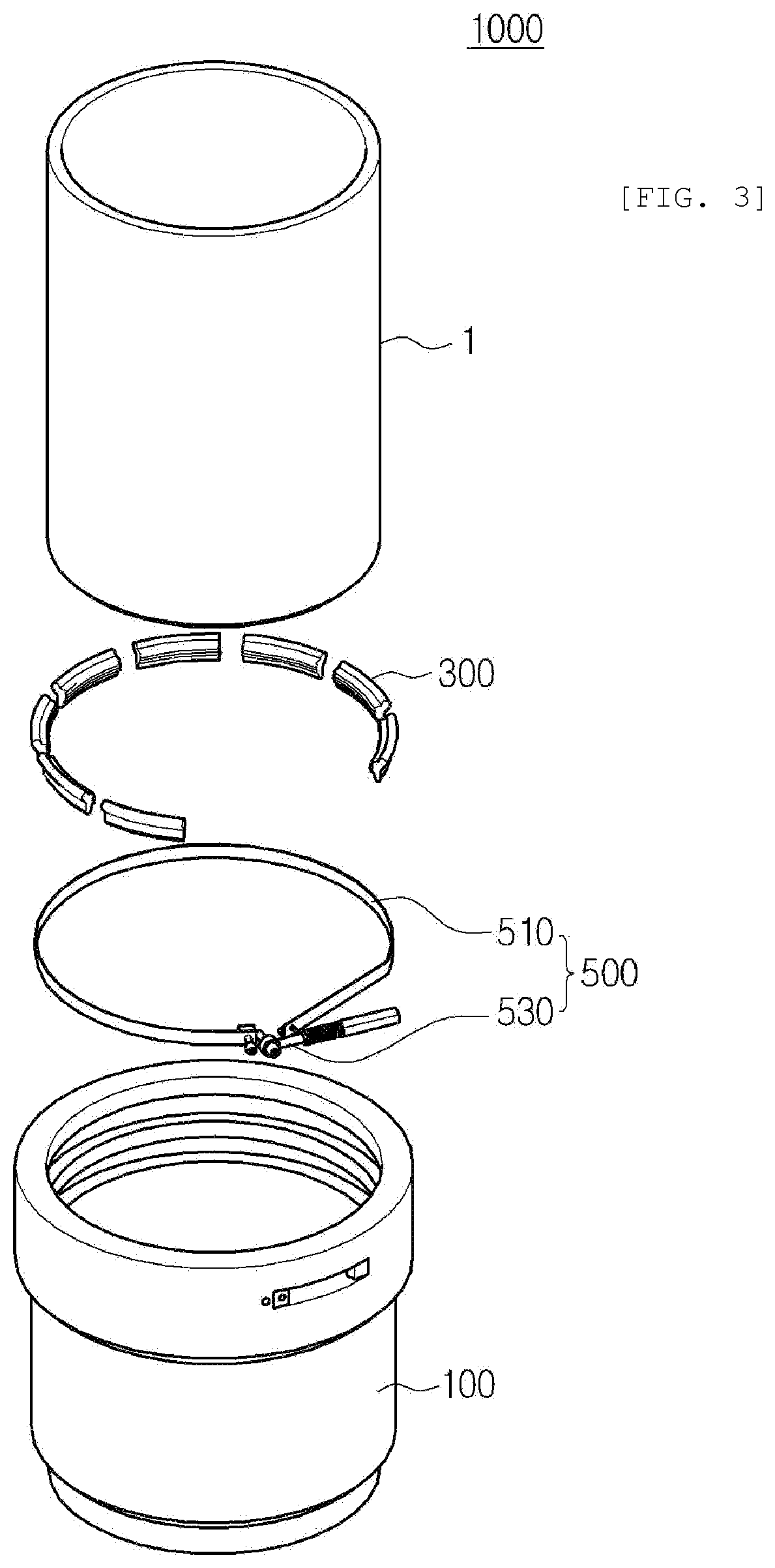
[0047]In the present specification, in adding reference numerals for elements in each drawing, it should be noted that like reference numerals already used to denote like elements in other drawings are used for elements wherever possible.

[0048]The terms described in the present specification should be understood as follows.

[0049]The singular forms are intended to include the plural forms as well, unless the context clearly indicates otherwise, and the scope of right should not be limited by these terms.

[0050]It should be understood that the terms “comprise” or “have” do not preclude the presence or addition of one or more other features, integers, steps, operations, components, elements, or combinations thereof.

[0051]Hereinafter, preferred embodiments of the present disclosure designed to solve the tasks will be described in detail with reference to the accompanying drawings.

[0052]Hereinafter, a pivot brace type pipe fitting according to an embodiment of the present disclosure will ...


PUM


Abstract

The present disclosure provides a pivot brace type pipe fitting, including: a body accommodating an entering pipe, and having a pivot corner having an inverted L-shaped cross section in an annular space surrounding a circumferential surface of the pipe; a plurality of pivot braces which are separated from an inside of the body and include a body adhesion unit in contact with the pivot corner and a pipe adhesion unit in contact with the pipe; and a pivot actuating member having a tightening strap surrounding the pivot brace and an actuator tightening the tightening strap, and bringing the pipe adhesion unit into close contact with the pipe by using the body adhesion unit as a pivot axis and pivoting the pivot brace.

Description

BACKGROUND OF THE INVENTION1. Technical Field[0001]The present disclosure relates to a pivot brace type pipe fitting, and more particularly, to a pivot brace type pipe fitting capable of easily and securely connecting pipes.2. Description of Related Art[0002]Various technologies such as welding, screw coupling, and flange coupling are used to connect pipes carrying a fluid such as water, and recently, research into a method for easily connecting pipes through a simple connecting device is being conducted.[0003]As a representative example of the related art, a pivot brace type pipe fitting according to the related art is disclosed in Korean Patent Application No. 10-2016-0082923.[0004]FIG. 1 is a schematic exploded perspective view illustrating a pivot brace type pipe fitting according to the related art. FIG. 2 is a schematic cross-sectional view in the width direction illustrating the coupled appearance of FIG. 1.[0005]As can be seen from FIGS. 1 and 2, the pivot brace type pipe fi...

Claims


Application Information

Patent Timeline
Patent Type & Authority Applications(United States)
IPC IPC(8): F16L37/092F16L37/084
CPCF16L37/092F16L37/0844F16L37/0842
Inventor KIM, SUK YOONKIM, YUSIE
Owner KIM SUK YOON
Why Eureka
Try Eureka