Apparatus and method for determining a rotational speed of at least one wheel of a vehicle

Pending Publication Date: 2022-03-03
KNORR-BREMSE SYST FUER NUTZFAHRZEUGE GMBH
View PDF0 Cites 0 Cited by
  • Summary
  • Abstract
  • Description
  • Claims
  • Application Information

AI Technical Summary

Benefits of technology

The patent describes a way to have a redundant sensor for measuring rotational speed, which can be used in braking systems or other applications. This means that the sensor can be used in multiple control units, making it more reliable and economical. The control units can also communicate with each other to determine the rotational speed in case of failure or disturbanvention. The main technical effect is to provide a simple and cost-effective way to have a redundant sensor for measuring rotational speed.

Problems solved by technology

Conventional fallback levels cannot therefore be used in critical situations.

Method used


Image

  • Apparatus and method for determining a rotational speed of at least one wheel of a vehicle
  • Apparatus and method for determining a rotational speed of at least one wheel of a vehicle

Examples


Embodiment Construction

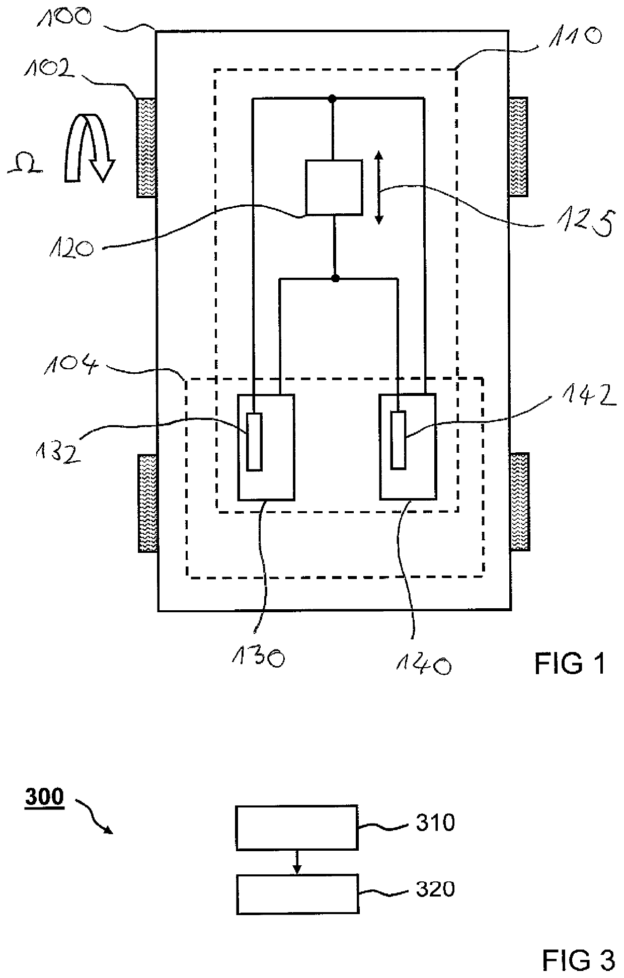
[0028]FIG. 1 shows a schematic illustration of a vehicle 100 with an apparatus 110 for determination according to one exemplary embodiment. The vehicle 100 is a motor vehicle, for example a commercial vehicle, in particular a truck or the like. The vehicle 100 comprises a plurality of wheels 102. For reasons of clarity, only one wheel 102 is drawn explicitly in the illustration of FIG. 1. The wheel 102 can turn with an angular velocity Ω that is correlated to a rotational speed of the wheel 102.

[0029]The vehicle 100 comprises the apparatus 110 for determination, or a determination apparatus 110. The determination apparatus 110 is configured to determine the rotational speed of the wheel 102 or a plurality of wheels 102 of the vehicle 100. According to the exemplary embodiment illustrated here, the determination apparatus 110 comprises a detection device 120, a first control unit 130 and a second control unit 140. The detection device 120 is only shown here for one wheel, although th...


PUM


Abstract

An apparatus for determining a rotational speed of at least one wheel of a vehicle, including: a detection device for detecting an angular velocity of the wheel that is correlated to the rotational speed, wherein the detection device is configured to provide an electrical detection signal depending on the angular velocity detected; a first control unit with a first measurement device for measuring the detection signal, wherein the first control unit is electrically joined to the detection device; and a second control unit with a second measurement device for measuring the detection signal, wherein the second control unit is electrically joined to the detection device, wherein the detection device can be electrically switched or is electrically switched between the first measurement device and the second measurement device. Also described is a related method.

Description

FIELD OF THE INVENTION[0001]The present invention relates to an apparatus for determining a rotational speed of at least one wheel of a vehicle and to an associated method.BACKGROUND INFORMATION[0002]In highly automated driving a driver of a vehicle does not, for example, have to sit permanently in a driver's seat and be available for a corrective manipulation. Conventional fallback levels cannot therefore be used in critical situations. If a primary braking system is not available, a redundant braking system should take over the driver's tasks. If redundancy is present, then in order, for example, to model ABS functionality, both brake systems should, conventionally, read signals from rotational speed sensors of wheels.SUMMARY OF THE INVENTION[0003]Against this background it is an object of the present invention to create an improved apparatus for determining a rotational speed of at least one wheel of a vehicle and an improved method for determining a rotational speed of at least ...

Claims


Application Information

Patent Timeline
IPC IPC(8): B60T8/88B60T8/171
CPCB60T8/885B60T2270/414B60T2270/413B60T8/171B60T8/88F16D2066/003
Inventor KAUFMANN, CHRISTIANHECKER, FALK
Owner KNORR-BREMSE SYST FUER NUTZFAHRZEUGE GMBH
Why Eureka
Try Eureka