Bed exit monitoring

Pending Publication Date: 2022-03-10
RESPONSE TIMES LTD
0 Cites 0 Cited by

AI-Extracted Technical Summary

Problems solved by technology

With particular respect to elderly patients, falls in hospital or other care environments are a significant cause of further injury or recovery setbacks.
In many instances, a fall leads to a serious injury, such as a hip fracture.
This can significantly and permanently reduce mobility and independence increasing the risk of other health complications up to and including premature death.
Such systems are not ideal as it can be difficult to distinguish between activities indicative of a bed exit attempt and other benign patient movement using such sensors.
Additionally, it can be relatively costly or difficult to retrofit such sensors to exis...

Benefits of technology

[0057]The device of the fifth aspect of the invention can improve the environment for the bed occupant and may further...

Abstract

A bed exit detection device (100) according to an embodiment of the present invention is mounted to a privacy rail (11) provided in the vicinity of a bed (10) to be monitored. The device (100) comprises a thermographic sensor (130) and a range sensor (40). The thermographic sensor comprises an array of sensing elements operable to generate an output value matrix from the output signals of each individual sensing element. The device (100) is also provided with a processing unit (150) operable to process the output value matrix of the thermographic sensor (130) and the distance output by the range sensor (140) so as to determine the position of a bed occupant and thereby (10) determine the likelihood of a bed exit event.

Application Domain

Medical imagingTemperature sensors +3

Technology Topic

EngineeringReal-time computing +5

Image

  • Bed exit monitoring
  • Bed exit monitoring
  • Bed exit monitoring

Examples

  • Experimental program(1)

Example

[0058]In order that the invention may be more clearly understood one or more embodiments thereof will now be described, by way of example only, with reference to the accompanying drawings, of which:
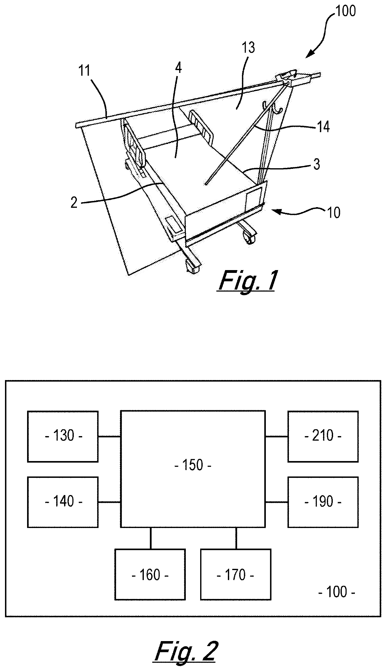
[0059]FIG. 1 is a schematic illustration of a bed exit detection device fitted to a bed;
[0060]FIG. 2 is a schematic block diagram of the bed exit detection device of FIG. 1;
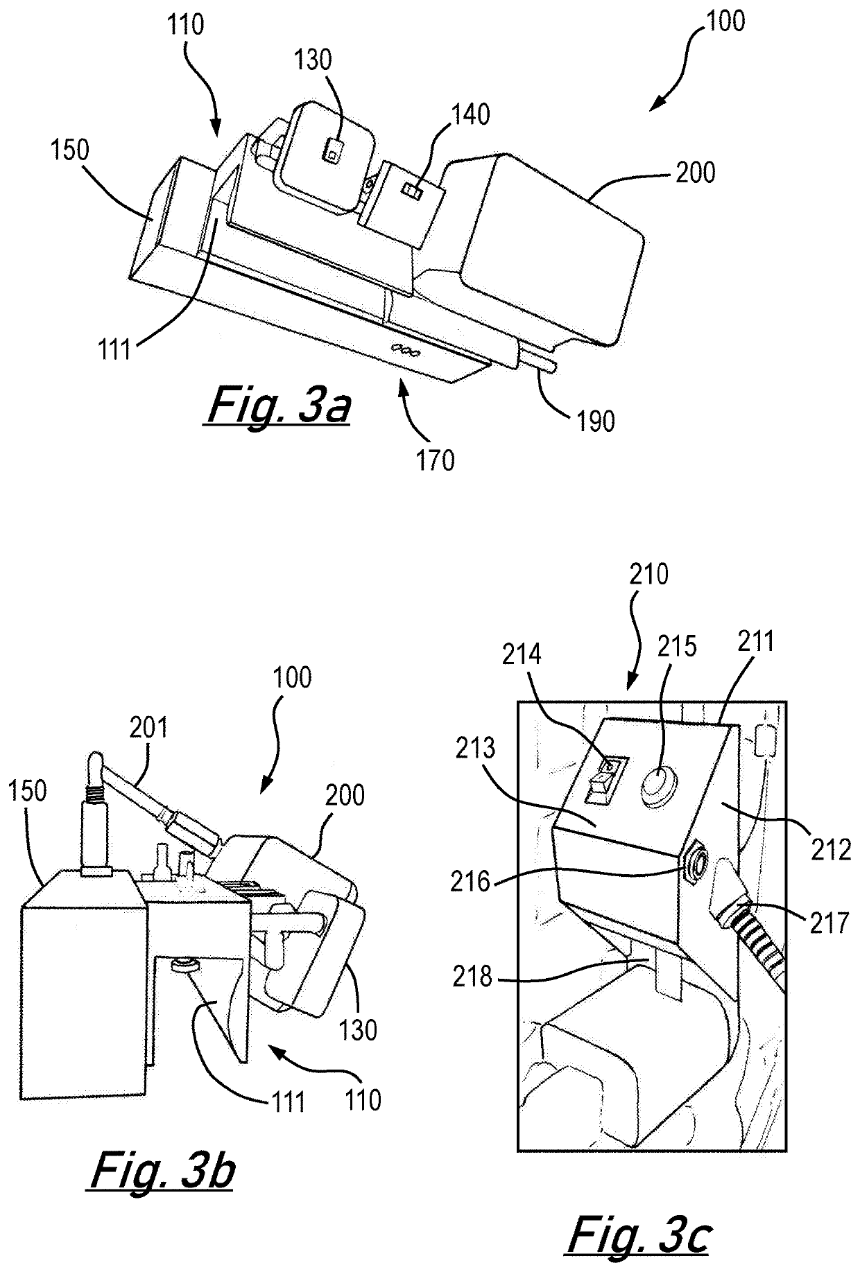
[0061]FIG. 3 shows (a) a front and side perspective view of the bed exit detection device of FIG. 1, (b) a side view of the bed exit detection device of FIG. 1; and (c) a perspective view of a user interface unit of the bed exit detection device of FIG. 1;
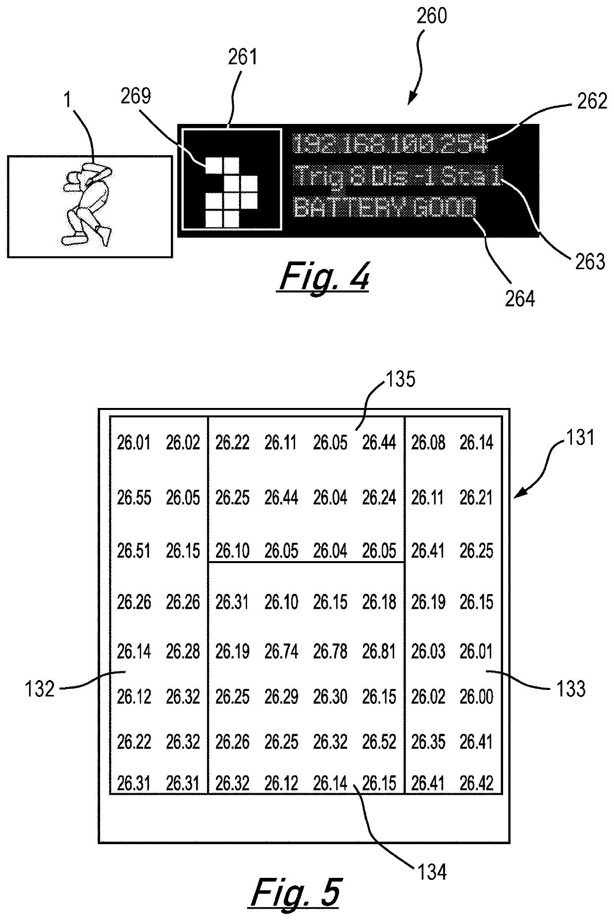
[0062]FIG. 4 is schematic illustration of the output of a display unit of a bed exit monitoring device;
[0063]FIG. 5 is a schematic illustration of different detection zones of an output value matrix of thermographic sensor for a bed exit detection device;
[0064]FIG. 6 is a schematic illustration of processed output value matrices so as to indicate both occupied and unoccupied segments in a series of different bed occupancy states;
[0065]FIG. 7 is a flow chart illustrating one implementation of a bed exit detection method;
[0066]FIG. 8 is a schematic illustration of a system for monitoring multiple bed exit monitoring devices; and
[0067]FIG. 9 is a schematic illustration of the display of a control console in the system of FIG. 8.
[0068]Turning to FIG. 1, a bed exit detection device 100 according to an embodiment of the present invention is mounted to a privacy rail 11 provided in the vicinity of a bed 10 to be monitored. The bed comprises a right edge 2, a left edge 3 and a centre 4. The mounting is achieved by way of a bracket 110, which in this embodiment comprises a slot 111 which in use engages the privacy rail 11. The device 100 is operable to monitor determine the position of a bed occupant 1 (not shown in FIG. 1) and thereby determine the likelihood of a bed exit event. Detecting such events can enable intervention by carers to avert potential negative consequences of bed exit by an elderly or infirm bed occupant 1.
[0069]The device 100 comprises a thermographic sensor 130 comprising an array of sensing elements, each sensing element operable to output signals corresponding to the temperature of a corresponding segment within the field of view 13 of the thermographic sensor 130. In use, the thermographic sensor 130 is operable to generate an output value matrix from the output signals of each individual sensing element. The output value matrix thus provides a map of the temperature of different segments within the field of view 13 of the thermographic sensor 130. The field of view 13 of the thermographic sensor 130 is illustrated schematically in FIG. 1. When the device 100 is positioned appropriately, the field of view 13 includes the bed 10 and both edges of the bed 2, 3. Accordingly, the thermographic sensor 130 can thus generate a segment by segment temperature map of bed 10 and an occupant 1 lying anywhere on the bed 10 and/or an occupant sitting anywhere on the bed 10. As such, temperature of each segment in the output value matrix can be used to determine whether each segment is aligned with occupant 1 of the bed 10 or the bed 10 itself.
[0070]As is illustrated in FIG. 1, the device 100 is also provided with a range sensor 140 operable to detect the distance between the device 100 and an object such as a bed occupant 1. The range sensor 140 is operable to output a beam 14 and detect reflections of the beam, determining range by calculating the time of flight of the reflected beam. In the embodiment shown in FIG. 1, the range sensor 140 is operable only to detect objects up to a maximum range illustrated by the extent of beam 14 in FIG. 1. This maximum range is in the region of the centre of the bed 10. Additionally, the range sensor 140 is aligned such that it does not detect an occupant 1 lying on the bed 10 but does detect an occupant 1 sitting on the bed 10, within the detection range.
[0071]Turning to FIG. 2, the device 100 comprises a processing unit 150 operable to process the output value matrix and the output of the range sensor 140 so as to determine the position of a bed occupant 1 and thereby determine the likelihood of a bed exit event.
[0072]In addition to the sensors 130, 140 and processing unit 150 the embodiment of the device 100 shown in FIG. 2 may additionally comprise a communication unit 160, indicator lamps 170, power source 190 (wired or battery, as required or desired) and interface unit 210. The skilled man will appreciate that the interface unit 210 may be provided adjacent to the other components or separately from the other components, as convenient.
[0073]The communication unit 160 is operable to enable signals to be exchanged wirelessly with one or more additional devices in a system 1000 as will be described in more detail below. The communication unit 160 is typically a WiFi transceiver but may be operable in accordance with any other data communication protocol as necessary. This facilitates the embodiment of the device 100 shown in FIG. 2 to communicate via a local WiFi network.
[0074]The indicator lamps 170 are operable to display device status. In the illustrated embodiment, the indicator lamps 170 comprise one red, one yellow and one green LED (light emitting diode). The red LED indicates the device 100 has power, the yellow LED indicates data transmission status, and the green LED indicates local WiFi network connectivity. The power source 190 is a wired 5 v connection. The input means 210 enables operation of the device 100 to be controlled.
[0075]Turning now to FIGS. 3a and 3b, an embodiment of the invention is shown that is designed to be fitted to a bed privacy rail 11 (not shown in FIG. 3a-c). In this example, elongate bracket 110 comprises an inverted U-shaped cross-section slot 111 that engages the privacy rail 11. Processing unit 150 is fitted to one side of the bracket 110. At one end of the processing unit 150, a wired connection provides the power source 190 and relays signals between the device 100 and interface unit 210 (described later). LED indicator lamps 170 are disposed on the housing of the processing unit 150. The thermographic sensor 130 and range sensor 140 are disposed on the opposite side of the bracket 110 from the processing unit 150.
[0076]In this embodiment, the device 100 is also fitted with an illumination unit 200. A front face of the illumination unit 200 is fitted with a translucent diffuser. The illumination unit 200 is powered via power lead 201 which connects to the processing unit 150. The illumination unit 200 is disposed on the same side of the bracket 110 as the thermographic sensor 130 and the range sensor 140, such that it is operable to illuminate the bed 10. Typically, the illumination unit 200 may be operated so as to emit diffuse background or ambient illumination of the bed 10.
[0077]The thermographic sensor 130 and range sensor 140 are pivotally connected to the bracket 110. This can be achieved by provision of a hinge or other suitable connection. This allows the pitch of each sensor 130, 140 to be independently adjusted to optimise the orientation of each sensor for the position of the device 100 with respect to the bed 10 to be monitored and the local environment. The illumination unit 200 may be similarly mounted and adjusted as necessary.
[0078]Additionally, some embodiments of the device 100 may feature a microphone (not shown) configured to output a signal indicative of the local sound pressure to the processing unit 150. The microphone may be a directional microphone and may be mounted next to the thermographic sensor 130. In such embodiments, the processing unit 150 may determine the peak-to-peak sound pressure and use this to output a signal indicative of patient agitation. This can provide further information to carers on the wellbeing of the bed occupant.
[0079]Turning now to FIG. 3c, the embodiment shown in FIGS. 3a and 3b also features a user interface unit 210. As the bracket 110 secures the device high on the privacy rail of the bed, the interface unit 210 is provided separately from the device 100 to allow easy access for users. The interface unit 210 comprises a body 212 with a back 211 adapted to facilitate mounting to a bed or wall for easy access. The body 212 has a front face 213 on which is provided a switch 214 and a button 215. The switch 214 controls the operation of illumination unit 200. The button 215 starts and stops bed exit monitoring of the device 100. This allows the monitoring to be paused when the occupant needs to be moved or if the bed needs to be cleaned or bedding changed.
[0080]In one side of the body 212, a socket 216 is provided. This allows the device 100 to be connected to an external sensor such as chair pressure sensor (not shown) or other equipment as required or desired. The skilled man will appreciate that additional connection sockets may be provided if required. A wired power connection 217 may provide a power source 190 and wired data connection to the processing unit 150 and sensors 130, 140.
[0081]A power socket 218 allows the bed occupant to power or charge personal electronic devices, such as mobile phones, tablets or the like. This further improves the quality of life for the bed occupant as they have convenient access to electrical power.
[0082]The skilled man will appreciate that in alternative embodiments, the entire device 100, including both sensors 130, 140, processing unit 150 and interface unit 210 are provided in the same body and are mounted directly to the footboard of the bed. Whilst such embodiments are perhaps more convenient to fit, they are particularly susceptible to tampering with by the bed occupant whether wilfully or accidentally.
[0083]In certain embodiments of the invention, a display 260 is provided, either on the device 100 or on interface unit 210. An example of the information provided on such a display 160 is shown in FIG. 4. A portion 261 of the display is operable to display an image 269 indicative of the output value matrix. The displayed image 269 corresponds to the position of a bed occupant 1. In addition to the image 269, the display also provides information as to the device identity/location at 261. A user actuable input means (not shown) can be used to toggle between the IP address, MAC address and device identity number. The display 260 further provides at 263 information on the current sensitivity setting of the thermographic sensor 130, output of the range sensor 140 and status of the device 100. At 264, the display provides information on the status of power supply 190.
[0084]FIG. 5 is an illustration of the output value matrix 131. In this example, the output value matrix 131 is an 8 by 8 square array corresponding to an 8×8 square array of sensing elements making up the thermographic sensor 130. The skilled man will appreciate that arrays comprising different numbers of segments and or different configurations of segments may be utilised in the present invention. In any particular implementation the number of segments selected must be sufficient to enable different bed occupant 1 positions to be distinguished. Nevertheless, the skilled man will also appreciate that arrays featuring much larger numbers of segments result in a much greater processing load for the processing unit 150. This can increase the cost and complexity of the device 100 and have an adverse impact on power consumption.
[0085]The array shown in FIG. 5 is populated by output signal values for each segment. The output signal values are expressed in a temperature equivalent in degrees Celsius. The processing unit 150 is operable to receive the temperature equivalent values from the thermographic sensor 130 for each segment. The received outputs are subsequently processed to determine whether they fall within a characteristic range. Segment outputs falling within the characteristic range are associated with the bed occupant 1 and thus identified as occupied segments. Segment values falling outside the characteristic range are identified as unoccupied segments.
[0086]By considering the occupied segments and the output of the range sensor 140, the processing unit 150 is operable to estimate the position of a bed occupant and hence the likelihood of a bed exit event.
[0087]The characteristic range is defined by an upper threshold which is pre-set to a value greater than possible body temperature of a human. The lower threshold of the characteristic range is varied in response to the overall output of the thermographic sensor 130 and the sensitivity setting (an offset value) of the thermographic sensor 130. In a particular example, the lower threshold of the characteristic range is calculated from the sum of the lowest output value in the output value matrix and the sensitivity setting. The lowest output value is typically selected from the present output value matrix. In this context, it has been found that temperature fluctuations, such as transient hot or cold spots can occur intermittently. As such, revising the lower threshold of the characteristic range can minimise the impact of such events on the device 100.
[0088]Whilst many readily available thermographic sensors 130 have a sensitivity range from say 0° C. to 80° C., the typical normal bounds of the characteristic range in the present invention will be in the region of 18° C. to 42° C. Whilst the temperature of human skin in a healthy individual is typically in the range 35° C. to 39° C., a wider range of temperature variation can be expected in unhealthy, elderly or infirm individuals.
[0089]The outputs, as processed above can be output as the image 169 on the display 160. In order to determine the likely bed occupant position corresponding to each image 169, the processing unit 150 is operable to determine the proportion of occupied segments in a number of different zones.
[0090]In order to select a suitable sensitivity setting, a user can adjust the sensitivity whilst the bed 10 is occupied and whilst observing image 169. Firstly, the user reduces the sensitivity setting to a value where the image 169 contains substantially no occupied segments. Subsequently, the user increases the sensitivity setting until features corresponding to the position of the occupant 1 on the bed 10 are visible in image 169. The sensitivity may be set wirelessly using a control console 1200 or carer terminal 1300, which are described below, or any other suitable device, such as a laptop. Additionally or alternatively, the processing unit 150 may be operable to automatically adjust the sensitivity through analysis of the readings of the output value matrix. In such embodiments, the analysis may use machine learning.
[0091]In the example of FIG. 5, the array 131 is split into four zones 132-135. The zones comprise a right zone 132, a left zone 133, a centre zone 134 and a top zone 135. If the device 100 is positioned correctly, the right zone 132 corresponds to the right edge 2 of the bed 10 and areas above the right edge 2 of the bed 10. Similarly, the left zone 133 corresponds to the left edge 3 of the bed 10 and areas above the left edge 3 of the bed 10. The centre zone 134 corresponds to the centre 4 of the bed 10 and the top zone 135 corresponds to the area above the centre 4 of the bed.
[0092]The processing unit 150 is operable to determine the proportion of segments in each zone 132-135 that are occupied and compare this proportion to a zone threshold value. If the proportion exceeds the zone threshold value, the zone is determined to be occupied by the bed occupant. If the proportion is below the zone threshold value, the zone is determined to be unoccupied. By determining which zones are occupied and considering the output of the range sensor 140, the processing unit 150 can determine the likely position of the bed occupant 1. Based on the determined position, the processing unit can subsequently determine if a bed exit event is likely or in progress. The processing unit 150 may additionally consider the overall proportion of occupied segments in order to determine whether a determined position is potentially valid.
[0093]Typically, given that the zones 132-135 differ in size and since location within particular zones 132-135 can vary the likelihood of bed exit events, the zone threshold values can vary for different zones 132-135. In the present example, the zone threshold values for the right and left zones 132, 133 may be say 12.5, 18.75 or 25%; the zone threshold value for the centre zone 134 may be say 15%; and the zone threshold value for the top zone 135 may be say 1%.
[0094]Turning to FIG. 6, some basic examples of this determination are illustrated with respect to the example images 169 wherein occupied segments are white and unoccupied segments are black.
[0095]In FIG. 6a, only the centre zone 134 is occupied. The bed occupant 1 can therefore be determined to be lying in the centre 4 of the bed. Accordingly, a bed exit event is unlikely.
[0096]In FIG. 6b, the centre zone 134 and top zone 135 are both occupied. The bed occupant 1 can therefore be determined to be sitting up in the centre 4 of the bed. Accordingly, an imminent bed exit event is unlikely. Nevertheless, this may raise the prospect of a future bed exit event compared to the example of FIG. 6a.
[0097]In FIG. 6c, only the right zone 132 is occupied. The bed occupant 1 can therefore be determined to be on the right edge 2. Accordingly, a bed exit event to the right side of the bed is either in progress or imminent. In response to such a determination, the processing unit 150 may output an alarm signal via the communication unit.
[0098]In FIG. 6d, only the left zone 133 is occupied. The bed occupant 1 can therefore be determined to be on the left edge 3 of the bed. Accordingly, a bed exit event to the left side of the bed is either in progress or imminent. In response to such a determination, the processing unit 150 may output an alarm signal via the communication unit.
[0099]In some instances, the position of the bed occupant 1 may not be readily resolved. In such cases, the processing unit 150 may also consider the proportion of occupied segments overall and/or the output of range sensor 140.
[0100]In FIG. 6e, the right zone 132, centre zone 134 and top zone 135 are all occupied. Additionally, the range sensor 140 indicates that there is an object in the range 100-1000 mm from the device 100. The bed occupant 1 can therefore be determined to be on the right edge 2 of the bed and relatively close to the foot board 11. Accordingly, a bed exit event to the right side of the bed is either in progress or imminent. In response to such a determination, the processing unit 150 may output an alarm signal via the communication unit.
[0101]In FIG. 6f, the left zone 133, centre zone 134 and top zone 135 are all occupied. Additionally, the range sensor 140 indicates that there is an object in the range 100-1000 mm from the device 100. The bed occupant can therefore be determined to be on the left edge 3 of the bed and relatively close to the foot board 11. Accordingly, a bed exit event to the left side of the bed is either in progress or imminent. In response to such a determination, the processing unit 150 may output an alarm signal via the communication unit.
[0102]In FIG. 6g, no zones are occupied and no segments are occupied. Additionally, the range sensor 140 indicates that no objects are within detection range. Accordingly, the bed 10 may be determined to be vacant.
[0103]In FIG. 6h, no zones are occupied and but some segments are occupied. Additionally, the range sensor 140 indicates that that there is an object in the range 100-1000 mm from the device 100. Accordingly, the device 100 may determine that the view is blocked and may output a signal to this effect.
[0104]In FIG. 6i, all zones are occupied. Additionally, the range sensor 140 indicates that no objects are within detection range. Accordingly, the device 100 may determine that the device is not positioned or configured correctly and may output a signal to this effect.
[0105]In FIG. 6j, all zones are unoccupied. Additionally, the range sensor 140 indicates that that there is an object within 100 mm of the device 100. Accordingly, the device 100 may determine that the view is blocked and may output a signal to this effect. Similarly, if the range sensor 140 indicates that there is an object within 100 mm of the device 100 and the zones are occupied in accordance with any of FIGS. 6a-6d, the device 100 may also determine that the view is blocked and may output a signal to this effect.
[0106]In some embodiments, some of the segments may be assigned to a disabled zone. The processing unit 150 will not consider the output of the segments in the disabled zone. This can be particularly useful if there are additional heat sources close to the bed, such as a portable heater, or if areas outside the bed zone are within the detection area of the sensor 130. An example of an array 131 comprising a disabled zone 136 is illustrated in FIG. 6k. In this example, the disabled zone 136 is at the upper edge of the array 131, similar to the top zone 135 in the previous example but with greater lateral extent and a stepped boundary 137 on each edge. Such a disabled zone 136 omits from processing areas outside the bed 10 when the sensor 130 is mounted on a privacy rail 11.
[0107]An example of an algorithm by which processing unit 150 may make such determinations is illustrated in FIG. 7. At s101 output values from the thermographic sensor 130 and range sensor 140 are received and processed so as to determine the occupied segments, occupied zones and whether any object is present within the detection range of the range sensor 140.
[0108]If the range value is less than a minimum at s102, the device 100 may be determined to be blocked and a signal to this effect may be output at s103.
[0109]If the range value is within the detection range of the device at s104, the total proportion of occupied segments is considered. If at s105 the occupied segment proportion is greater than 90% the device 100 may be determined to be blocked and a signal to this effect may be output at s106. If at s107 the occupied segment proportion is less than 5% the device 100 may be determined to be blocked and a signal to this effect may be output at s108.
[0110]If the total proportion of occupied segments is between 5% and 90%, the relative proportion of occupied segments in each zone is considered at s109. If the relative proportions are not clearly greater to either side, the occupant position may be determined to be unresolved at s110. The process may then revert to s101.
[0111]If the relative proportions are clearly to either side at s111, the occupant position may be determined to be a bed exit risk to either side at s112 and s113. An alarm signal to this effect may be output.
[0112]If the range sensor 140 indicates that no objects have been detected in the detection range at s114, the total proportion of occupied segments is considered. If at s115 the occupied segment proportion is greater than 80% the device 100 may be determined to be misconfigured and a signal to this effect may be output.
[0113]If at s117 it is determined that the proportion of occupied segments in the centre zone 134 is less than 25%, then the proportion of occupied segments in the right zone 132 is considered s118. If this proportion is equal to or exceeds 30%, the occupant position may be determined to be a bed exit risk to the right side at s119. An alarm signal to this effect may be output.
[0114]If the proportion of occupied segments in the right zone 132 is less than 30%, then the proportion of occupied segments in the left zone 133 is considered at s120. If this proportion is equal to or exceeds 30%, the occupant position may be determined to be a bed exit risk to the left side at s121. An alarm signal to this effect may be output.
[0115]If the proportion of occupied segments in the left zone 133 is also less than 30%, then the bed may be determined to be unoccupied at s 122. A signal to this effect may be output.
[0116]In embodiments where the top zone 135 is in operation, if at s117 it is determined that the proportion of occupied segments in the centre zone 134 is greater than 25%, then the existence of occupied segments in the top zone 135 is considered at s123. If there are no occupied segments in the top zone 135, then the occupant position may be determined to be lying in the centre of the bed at s124. A signal to this effect may be output.
[0117]If at s123 there are no occupied segments in the top zone 135 then the relative proportion of occupied segments in the top zone 135 is considered at s125. If the proportion of occupied segments is less than 80%, then at step s126 the occupant may be determined to be sitting position. A signal to this effect may be output. Alternatively, if the proportion of occupied segments is greater than or equal to 80%, then at step s127 the occupant may be determined to be sitting position and partially blocking the device view. A signal to this effect may be output.
[0118]In embodiments having a disabled zone 136 in place of a top zone 135, s123 and s124 are omitted. Instead, the method proceeds directly from s117 to s125.
[0119]In optional embodiments, as shown in FIG. 7, a chair pressure sensor may also be in communication with device 100 via communication unit 180. In such cases, the processing unit 150 may also be operable to determine if there is a change in the output of the chair pressure sensor at s128. Depending on the nature of the change in output of the chair pressure sensor, the chair can either be determined to be occupied at s129 or unoccupied at s130. A signal to this effect may be output. In use, multiple devices 100 (100-01 to 100-04) may be fitted to multiple beds 1, say within a hospital ward or care home, as shown in FIG. 8. The devices 100 may be monitored using a system 1000 comprising a routing hub 1100 which is operable to enable transmission of signals between multiple devices 100 and a control console 1200. The control console 1200 typically comprises a tablet computer. The control console 1200 has a display 1210 operable to display information relating to the current status detected by each device 100, as determined by signals received by the control console 1200.
[0120]An enlarged example of display 1210 is shown at FIG. 9. The display 1210 has a first portion 1220 displaying information as to the operation of the system as a whole. This information may include current date and time 1221, number of current bed exit alarms 1222, a map 1223 of the location of beds and a log 1224 of recent status updates. The display has a second portion 1230 containing information about the current status of each device 100. In particular, this may include a status icon 1231, a trace line 1232 indicating recent changes in the output value matrix, a sensor battery heath icon 1233 and bed/patient identity information 1234.
[0121]In the event that a bed exit event is detected by one of the devices 100, say device 100-04 in FIG. 8, an alarm signal is output. The alarm signal is received at the control console 1200 and the status information relating to device 100-04 is updated. Additionally, a corresponding alarm signal is output by the control console to one or more carer terminals 1300.
[0122]The carer terminals 1300 are provide with at least a display 1310. The carer terminals are typically small tablet computers adapted to be carried by members of the care staff in the ward or care home. Upon receipt of the alarm signal, the carer terminals 1300 output an alarm. Typically, this might include an audio signal and or vibration in addition to information displayed on the display 1310. The display 1310 is operable to display details of the alarm such as the identity of the bed 10, device 100 or bed occupant 1, the location of the bed 10 and the nature of the detected bed exit event. The carer can thus go to the bed 10 and attempt to avert or alleviate the detected bed exit event.
[0123]Typically, the carer terminal 1300 is also operable to enable an input to be made in response to an alarm. This can allow a carer to acknowledge receipt of the alarm and/or indicate whether they are responding. This acknowledgment can be transmitted back to the control console 1200. This can enable a record of response activity to be maintained. It may also enable the alert to be cancelled for other carer terminals 1300 once one acknowledgment is received. This can avoid diverting multiple members of staff unnecessarily. Additionally or alternatively, an acknowledgement may be made directly using control console 1200.
[0124]In use, as an initial step s1001, each device 100 is set up. This involves mounting the device securely relative to a bed 10, adjusting the sensitivity setting of each device 100, adjusting the allocation of zones to each segment of the thermographic sensor 130 and ensuring each device 100 is in communication with the control console 1200. Additionally, each carer terminal 1300 may also be set up and put in communication with the control console 1200. Subsequently monitoring operation can commence at s1002. This monitoring typically includes each device 100 transmitting status messages to the control console 1200 as required.
[0125]In the event that a bed occupant 1 makes a bed exit attempt at s1003, the corresponding device 100 detects the variation in the output value matrix and/or the range sensor output at s1004. The processing unit 150 processes these outputs to determine that a bed exit attempt is in progress at s1005. Consequently, an alarm signal is output to the control console 1200 at s1006.
[0126]The alarm signal results in an alarm being output by the control console 1200 at s1007. This alarm can be output on display 1210 at s1008. The alarm is also transmitted to carer terminals 1300 such that these terminals 1300 also output the alarm at s1009. Additionally, details of the alarm may be transmitted to an archive terminal or a supervisor or a computer or mobile device of a supervisor at s1010. If no acknowledgement is made using carer terminals 1300 or control console 1200 then this lack of action is communicated to the archive terminal, supervisor or computer/mobile device of the supervisor at s1011.
[0127]If an acknowledgment is made at s1012, the control console 1200 can output the acknowledgement at s1013 and the acknowledgement can be communicated to the archive terminal, supervisor or computer/mobile device of the supervisor at s1014. The carer who made the acknowledgement at s1012 can then attend to the bed occupant at s1015. Assuming timely response on the part of the carer, this can result in the bed exit attempt being resolved at s1016. Monitoring can then resume at s1002.
[0128]The one or more embodiments are described above by way of example only. Many variations are possible without departing from the scope of protection afforded by the appended claims.

PUM

no PUM

Description & Claims & Application Information

We can also present the details of the Description, Claims and Application information to help users get a comprehensive understanding of the technical details of the patent, such as background art, summary of invention, brief description of drawings, description of embodiments, and other original content. On the other hand, users can also determine the specific scope of protection of the technology through the list of claims; as well as understand the changes in the life cycle of the technology with the presentation of the patent timeline. Login to view more.

Similar technology patents

Open irrigated ablation catheter

ActiveUS20140276758A1reduce likelihoodreduce impedance
Owner:BOSTON SCI SCIMED INC

System for Tracking Surgical Objects

ActiveUS20140303606A1reduce likelihood
Owner:GARNER RICHARDS STEVEN

Method of conducting financial transactions

InactiveUS20120005096A1reduce fraudreduce likelihood
Owner:SQUARE

Classification and recommendation of technical efficacy words

  • improve environment
Why Eureka
Try Eureka