Systems and methods for a stationary ct imaging system

Active Publication Date: 2021-12-09
GE PRECISION HEALTHCARE LLC
View PDF1 Cites 0 Cited by
  • Summary
  • Abstract
  • Description
  • Claims
  • Application Information

AI Technical Summary

Benefits of technology

[0005]In one aspect, a method for a stationary computed tomography (CT) system includes activating an emitter of a plurality of emitters of a stationary distributed x-ray source unit to emit an x-ray beam toward an object within an imaging volume, where the x-ray source unit does not rotate around the imaging volume, receiving the x-ray beam at a subset of detector elements of a plurality of detector elements of one or more detector arrays, sampling the plurality of detector elements to generate a total transmission profile, an attenuation profile, and a scatter measurement, generating a scatter-corrected attenuation profile by entering the total transmission profile, the attenuation profile, and the scatter measurement as inputs to a model, and reconstructing one or more images from the scatter-corrected attenuation profile. In this way, the stationary CT system may be used to non-invasively image a subject without relying on moving parts, particularly a rotating gantry, and thus may be smaller and lighter weight, expanding the environments in which the CT system may be deployed. However, because the stationary CT system includes detector elements that receive attenuated x-ray beams from more than one

Problems solved by technology

However, because the stationary CT system includes detector elements that receive attenuated x-ray beams from more than one emitter, conventional anti-scatter grids that are positioned between the detector elements and

Method used


Image

  • Systems and methods for a stationary ct imaging system
  • Systems and methods for a stationary ct imaging system
  • Systems and methods for a stationary ct imaging system

Examples


Embodiment Construction

[0066]Embodiments of the present disclosure will now be described, by way of example, with reference to the FIGS. 1-57, which relate to various embodiments for stationary computed tomography (CT) imaging systems.

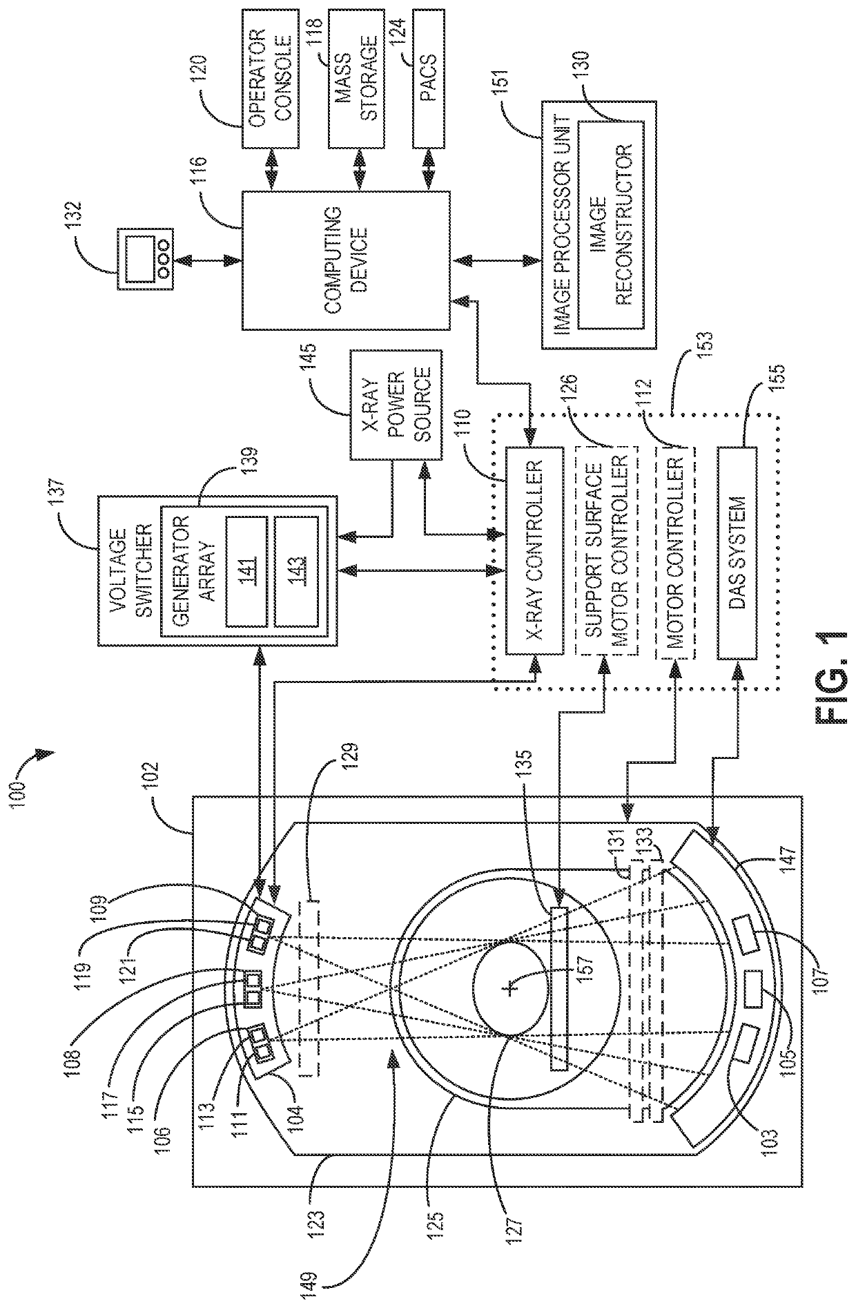
[0067]FIG. 1 illustrates an exemplary imaging system 100 configured for CT imaging. Particularly, the imaging system 100 is configured to image a subject 127. Subject 127 may be a patient, an inanimate object, one or more manufactured parts, and / or foreign objects such as dental implants, stents, and / or contrast agents present within the body. In one embodiment, the imaging system 100 includes a frame 102, which in turn, may further include at least one distributed x-ray source unit 104 configured to project x-ray radiation for use in imaging the subject 127 supported by a support surface 135. Specifically, the distributed x-ray source unit 104 is configured to project x-ray radiation beams 149 towards a detector array 147 positioned on the opposite side of the frame 102, wi...


PUM


Abstract

Various methods and systems are provided for stationary CT imaging. In one embodiment, a method for an imaging system includes activating an emitter of a plurality of emitters of a stationary distributed x-ray source unit to emit an x-ray beam toward an object within an imaging volume, where the x-ray source unit does not rotate around the imaging volume, receiving the x-ray beam at a subset of detector elements of a plurality of detector elements of one or more detector arrays, sampling the plurality of detector elements to generate a total transmission profile, an attenuation profile, and a scatter measurement, generating a scatter-corrected attenuation profile by entering the total transmission profile, the attenuation profile, and the scatter measurement as inputs to a model, and reconstructing one or more images from the scatter-corrected attenuation profile.

Description

CROSS REFERENCE TO RELATED APPLICATIONS[0001]This application claims priority to U.S. Provisional Patent Application No. 63 / 036,162, titled “A TRANSPORTABLE AND AUTONOMOUS STATIONARY CT IMAGING SYSTEM,” and filed Jun. 8, 2020; U.S. Provisional Patent Application No. 63 / 036,272, titled “AN UPRIGHT STATIONARY CT IMAGING SYSTEM AND IMAGE RECONSTRUCTION FOR SAME,” and filed Jun. 8, 2020; U.S. Provisional Patent Application No. 63 / 036,203, titled “A DISTRIBUTED X-RAY SOURCE FOR AN IMAGING SYSTEM,” and filed Jun. 8, 2020; U.S. Provisional Patent Application No. 63 / 039,071, titled “A STATIONARY CT IMAGING SYSTEM AND SCATTERED X-RAY RADIATION,” and filed Jun. 15, 2020; and U.S. Provisional Patent Application No. 63 / 039,181, titled “A MULTI-ENERGY STATIONARY CT IMAGING SYSTEM,” and filed Jun. 15, 2020. The entire contents of each of the above-identified applications is hereby incorporated by reference for all purposes.FIELD[0002]Embodiments of the subject matter disclosed herein relate to co...

Claims


Application Information

Patent Timeline
IPC IPC(8): A61B6/00A61B6/03G06T11/00
CPCA61B6/5282A61B6/4266G06T2211/40A61B6/4078G06T11/003A61B6/032A61B6/4405A61B6/4275A61B6/4014A61B6/4007A61B6/5264A61B6/4476A61B6/0407A61B6/4452A61B6/4411A61B6/06G06T2211/412G06T7/20G06T11/006G06T2207/10081G06T2207/20081G06T2207/30004
Inventor DE MAN, BRUNO KRISTIAAN BERNARDPACK, JED DOUGLASWU, MINGYESMITH, CHAD ALLANTHIBAULT, JEAN-BAPTISTE
Owner GE PRECISION HEALTHCARE LLC
Why Eureka
Try Eureka