Gas turbine ejector

A gas turbine and ejector technology, which is applied in the direction of gas turbine devices, machines/engines, jet pumps, etc., can solve the problems of gas turbine back pressure, exhaust gas blocking and pressure suppression, and low ejection speed, and achieve compact structure and powder injection. The effect of increased injection volume and ejection speed, smaller volume and mass

Active Publication Date: 2021-12-10
贵州黎阳天翔科技有限公司
View PDF6 Cites 0 Cited by
  • Summary
  • Abstract
  • Description
  • Claims
  • Application Information

AI Technical Summary

Problems solved by technology

However, the existing gas turbine ejector has air resistance to the ejected airflow, the ejection speed is low, and it is easy to cause the exhaust gas of the gas turbine high-speed jet to be blocked and suppress the pressure, causing back pressure effects on the gas turbine

Method used


Image

  • Gas turbine ejector
  • Gas turbine ejector

Examples


Embodiment Construction

[0023] The following will clearly and completely describe the technical solutions in the embodiments of the present invention with reference to the accompanying drawings in the embodiments of the present invention. Obviously, the described embodiments are only part of the embodiments of the present invention, not all of them. Based on the embodiments of the present invention, all other embodiments obtained by persons of ordinary skill in the art without creative efforts fall within the protection scope of the present invention.

[0024] It should be noted that all directional indications (such as up, down, left, right, front, back...) in the embodiments of the present invention are only used to explain the relationship between the components in a certain posture (as shown in the accompanying drawings). Relative positional relationship, movement conditions, etc., if the specific posture changes, the directional indication will also change accordingly.

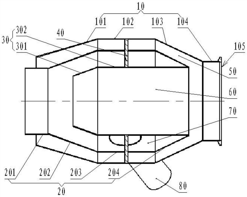
[0025] Such as figure 1...


PUM


Abstract

A gas turbine ejector comprises an outer shell, a middle shell, an inner shell and a powder feeding pipe. The right end of the outer shell is provided with an air inlet used for being connected with a gas turbine; the middle shell is arranged in the outer shell, and a gap exists between the middle shell and the outer shell to form a gas turbine tail gas auxiliary flow channel; the inner shell is arranged in the middle shell, and the right end part of the middle shell is connected with the right end of the inner shell; a gap exists between the middle shell and the inner shell to form a powder injection flow channel; the powder feeding pipe penetrates through the outer shell and the middle shell and is communicated with the powder injection flow channel; and a gas turbine tail gas main flow channel is arranged on the inner shell. Gas turbine high-speed jet tail gas is divided into two paths after entering the ejector, one path passes through the gas turbine tail gas main flow channel, the other path passes through the gas turbine tail gas auxiliary flow channel, and the gas turbine high-speed jet tail gas is branched, so that the gas turbine high-speed jet tail gas is prevented from blocking and pressure building, and the back pressure influence on the gas turbine is avoided.

Description

technical field [0001] The invention relates to the technical field of cigarette-generating vehicles, in particular to a gas turbine ejector for a cigarette-generating vehicle. Background technique [0002] The gas turbine ejector is an accessory of the smoke-generating vehicle of the smoke-generating force, and is mainly used to provide part of the power and flow path for the smoke-generating vehicle to generate infrared interference smoke screen. The smoke-generating vehicle can provide smoke screens and interference environments for relevant actual combat exercises of the troops, increase actual combat exercise items, simulate actual combat scenarios, and enrich the combat experience of combatants in smoke screens and interference environments. [0003] The gas turbine ejector is used for matching with small gas turbines. However, the existing gas turbine ejector has air resistance to the ejected airflow, the ejection speed is low, and it is easy to cause the high-speed ...

Claims


Application Information

Patent Timeline
Patent Type & Authority Applications(China)
IPC IPC(8): F02C7/00F01D25/30F04F5/36F04F5/44F04F5/54
CPCF02C7/00F01D25/305F04F5/36F04F5/44F04F5/54
Inventor 郑登强安旭松马关田冯德润
Owner 贵州黎阳天翔科技有限公司
Why Eureka
Try Eureka