

Magerle metal waste recovery process
- Summary
- Abstract
- Description
- Claims
- Application Information
AI Technical Summary
Benefits of technology
Problems solved by technology
Method used
Image

Examples
Embodiment Construction
ecome readily apparent upon further review of the following specification and drawings.
BRIEF DESCRIPTION OF THE DRAWINGS
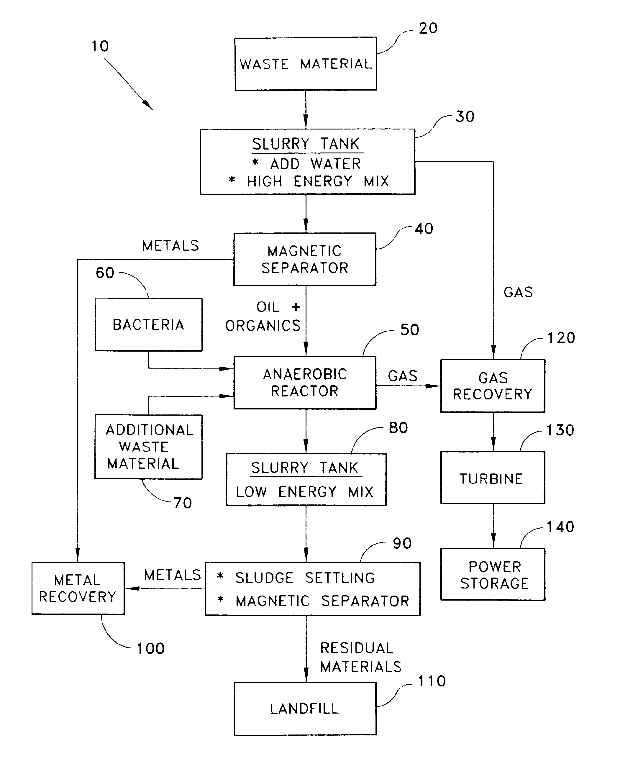
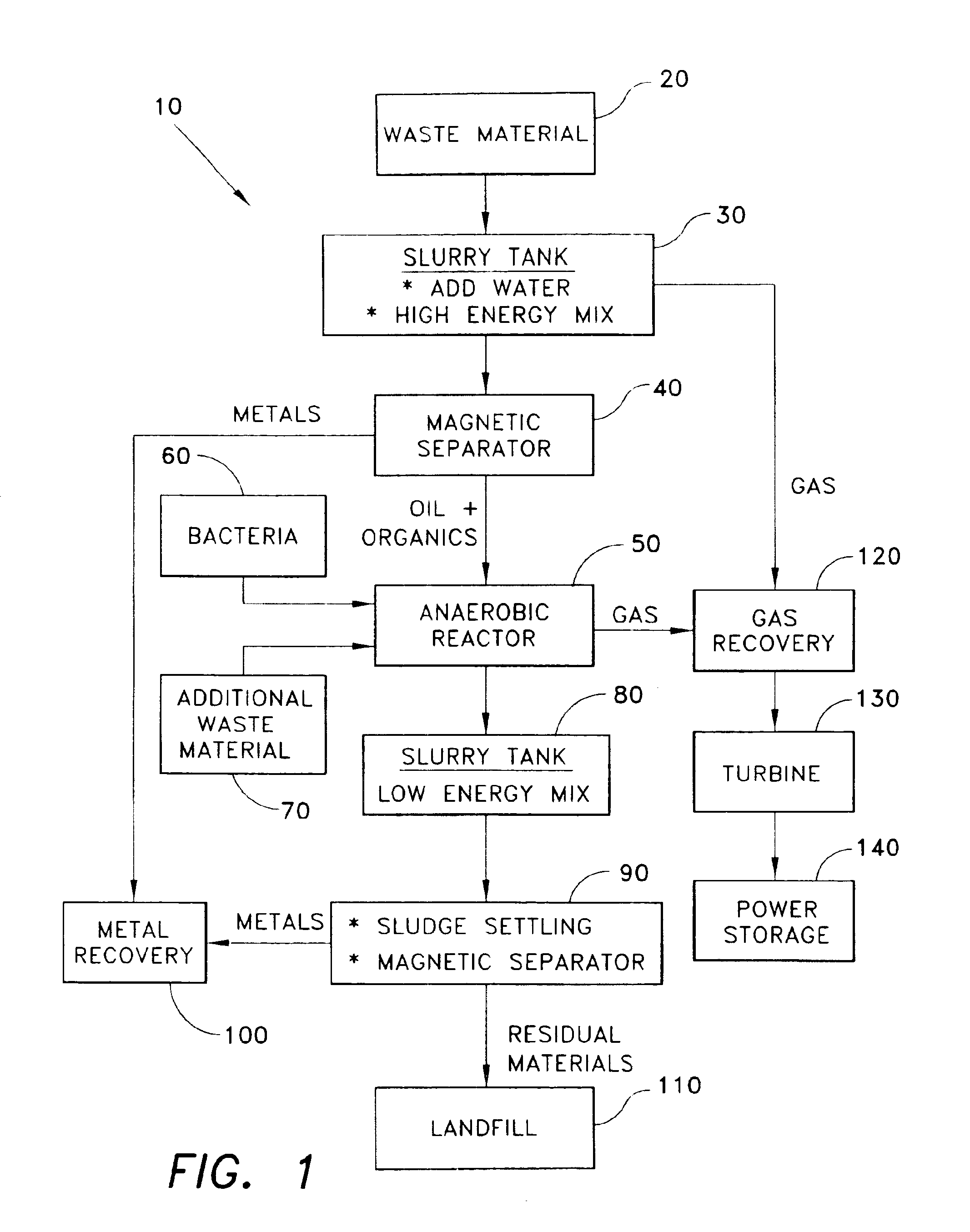
[0019]FIG. 1 is a process drawing showing the metal waste recovery process of the present invention.
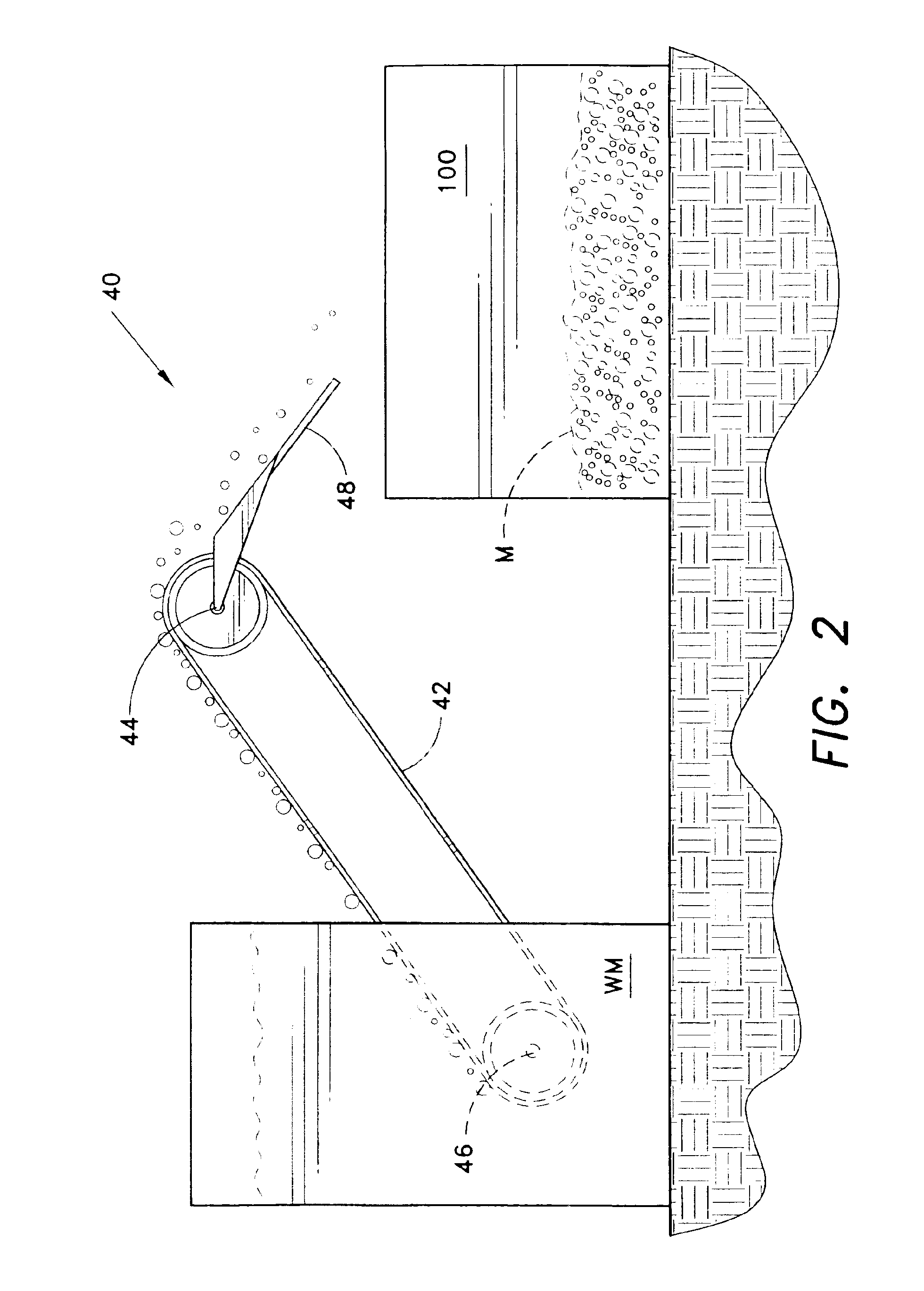
[0020]FIG. 2 is a side view of a magnetic metal separator.
[0021]Similar reference characters denote corresponding features consistently throughout the attached drawings.
DETAILED DESCRIPTION OF THE PREFERRED EMBODIMENTS
[0022]The present invention provides a process for recovering useful material from a quantity of waste material. The process is used to recover useful metal and gas from a sample of waste material. In particular, the process of the present invention is used to recover useful metal and gas from the cutting oil waste material produced by grinding metal with a Magerle heavy duty grinder. Magerle is Swiss maker of industrial grinding-systems and produces surface grinding machines, grinding centers and profile / creepfeed grinding machines. The process of the ...
PUM
| Property | Measurement | Unit |
|---|---|---|
| Angular velocity | aaaaa | aaaaa |
| Energy | aaaaa | aaaaa |
Abstract
Description
Claims
Application Information