
Electrical Component Enclosure and Method of Use

a technology of electrical components and enclosures, applied in the direction of printed circuit board receptacles, electrical apparatus casings/cabinets/drawers, casings/cabinets/drawers details, etc., can solve the problems of difficult and time-consuming process of using tools to actuate latch components, difficulty in visual confirmation of component engagement and actuation by tool blades, etc., to improve the effect of latch actuation and lid removal

Active Publication Date: 2022-03-17
PHOENIX CONTACT DEVMENT & MFG
View PDF5 Cites 0 Cited by
  • Summary
  • Abstract
  • Description
  • Claims
  • Application Information

AI Technical Summary

Benefits of technology

The patent is about a way to improve the way you can open and close an electrical component enclosure using a tool like a screwdriver. This makes it easier to remove the lid and access the components inside. The design allows for easier engagement and disengagement of the lid with the enclosure. This makes it safer and easier to work with the components inside.

Problems solved by technology

The process of using a tool to actuate latch components is problematic.
Properly locating a tool blade to actuate small latch components can be difficult and time-consuming.
As latch elements may be located within an enclosure recess or other protective structure to prevent inadvertent latch actuation, visual confirmation of component engagement and actuation by a tool blade is difficult or not possible in the field.
This can result in poor location of the tool blade.
When a disengagement force is applied to the tool, poor location of the tool blade can result in failed actuation of latch elements, undesired placement of the tool blade away from latch elements and potential damage to the enclosure or the components held therein.
The need to use two hands simultaneously to achieve lid removal complicates the procedure and further increases the risk for blade dislocation.

Method used


Image

  • Electrical Component Enclosure and Method of Use
  • Electrical Component Enclosure and Method of Use
  • Electrical Component Enclosure and Method of Use

Examples


Embodiment Construction

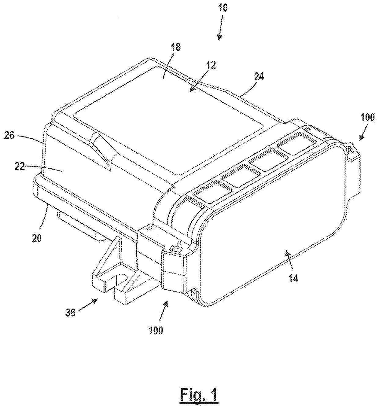
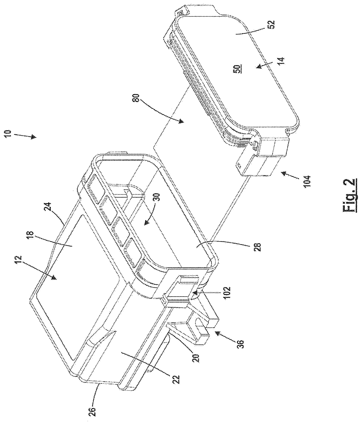
[0032]FIG. 1 shows an electrical component enclosure assembly 10 having an enclosure body 12 and an enclosure lid or faceplate 14. Enclosure body 12 and enclosure faceplate 14 may each be molded from plastic, other insulating materials or formed from metal.

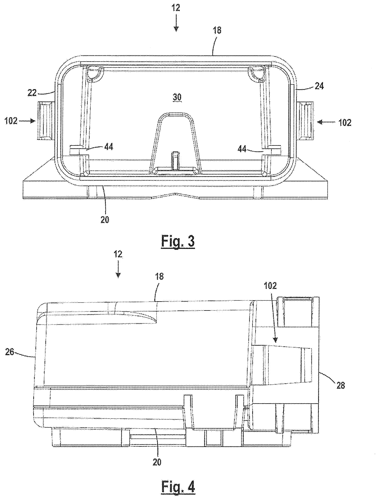
[0033]As shown in the figures, enclosure body 12 is generally rectangular in shape and is made up of five body walls: top wall 18, bottom wall 20, side walls 22, 24, and rear wall 26. Enclosure mouth opening 28 leads into enclosure internal cavity 30. The surrounding body walls define cavity 30 which has a generally rectangular shape, having a major axis 32 extending from the enclosure mouth 28 to rear wall 26 and a minor axis 34 extending between side walls 22, 24. Minor axis 34 extends generally parallel to enclosure mouth opening 28.

[0034]Two enclosure assembly feet 36 extend from the bottom of body 12 proximate enclosure body side walls 22, 24 and enclosure body bottom wall 20. Each foot 36 is generally rectangular in shape an...


PUM


Abstract

An enclosure assembly for housing printed circuit boards and related electrical components having a secured faceplate that may be removed by use of a hand tool.

Description

FIELD OF THE DISCLOSURE[0001]The disclosure relates to electrical component enclosures and in particular to latches for securing lids to electrical component enclosures.BACKGROUND OF THE DISCLOSURE[0002]Enclosures for housing electrical components such as printed circuit boards (PCBs), electronic modules and like electrical components are known. Enclosures are typically made of plastic or metal and are designed to house electrical components within a secured recess. The enclosures are adapted for installation in different indoor and outdoor environments to meet end application needs.[0003]It is known for electrical component enclosures to have removable faceplates or lids. Lids may be secured in place to an enclosure through the use of various kinds of retention latches.[0004]It is known to actuate latch components through the use of elongate tools having blade, such as a screwdriver to allow lid removal.[0005]The process of using a tool to actuate latch components is problematic. T...

Claims


Application Information

Patent Timeline
IPC IPC(8): H05K5/02H05K7/14
CPCH05K5/0221H05K5/0239H05K7/1427H05K7/1402H05K5/0217H05K7/14H05K7/1418H05K5/0013H05K5/03
Inventor RAIC, DEJANFARMER, STEVEN CHRISTOPHER
Owner PHOENIX CONTACT DEVMENT & MFG
Learn More