Water Insensitive Capacitive Sensor Switch

Active Publication Date: 2022-03-24
CAPTRON ELECTRONICS
View PDF0 Cites 0 Cited by
  • Summary
  • Abstract
  • Description
  • Claims
  • Application Information

AI Technical Summary

Benefits of technology

[0005]The embodiments are providing a capacitive proximity sensor provid

Problems solved by technology

A disadvantage is that a conductive liquid, for example water, on the sensor surface may have the same effect.
Accordingly, such a liquid may lead to a false triggering of the swi

Method used


Image

  • Water Insensitive Capacitive Sensor Switch
  • Water Insensitive Capacitive Sensor Switch
  • Water Insensitive Capacitive Sensor Switch

Examples


Embodiment Construction

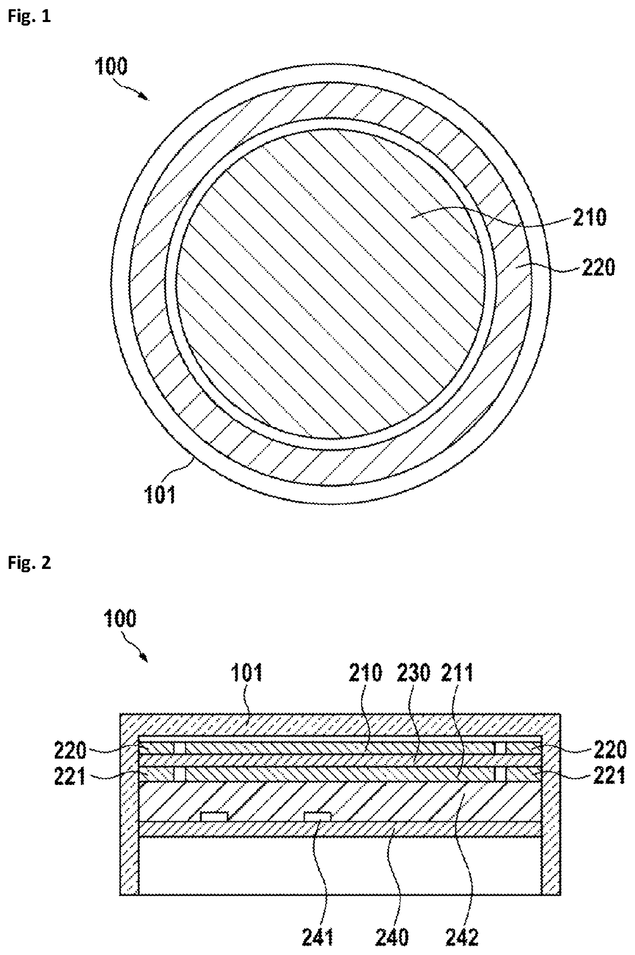
[0057]In FIG. 1, a top view on a sensor switch 100 is shown. The sensor switch 100 has a housing 101 and a first sensor electrode 210 which is surrounded by a second sensor electrode 220. Both sensor electrodes are in a common plane (arranged in the same plane). In a further embodiment, the second sensor electrode 220 is arranged between ground 190 and the first sensor electrode 210. This may be the case, if the switch is mounted in or on a grounded surface. There may also be a ground ring or ground plane at least partially surrounding the sensor electrode.

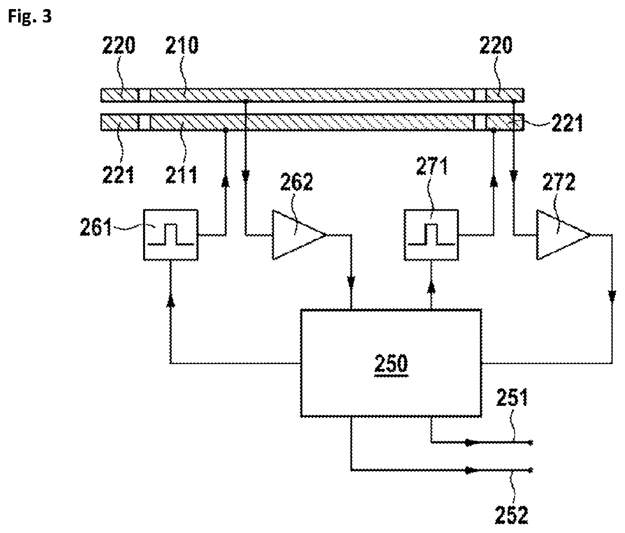
[0058]FIG. 2 shows a sectional side view of the sensor switch of FIG. 1. The housing 101 preferably has a cup shape. The housing 101 holds the first sensor electrode 210 and the second sensor electrode 220, which are preferably arranged on or are part of a printed circuit board 230. Preferably, close to the first sensor electrode 210, a first signal electrode 211 is arranged and a second signal electrode 221 is in close proximity ...


PUM


Abstract

A sensor switch including a first sensor electrode and a second sensor electrode at least partially surrounding the first sensor electrode. An evaluation and control circuit of the sensor switch is configured to generate a switch output signal if a first sensor electrode attenuation signal indicates a high signal attenuation, a second sensor electrode attenuation signal indicates a low signal attenuation, and a cross-coupling signal from the first to the second electrode indicates a low cross-coupling.

Description

CROSS-REFERENCE TO RELATED APPLICATIONS[0001]This application is a continuation of the pending International Application No. PCT / EP2020 / 062376 filed on 5 May 2020 and published as WO 2020 / 249306 on 17 Dec. 2020, which designates the United States and which claims priority from the European Application No. 19179739.8 filed on 12 Jun. 2019 and published as EP 3751740A1 on Dec. 16, 2020. The disclosure of each of the above-identified patent applications is incorporated by reference herein.BACKGROUND1. Field of the Invention[0002]The invention relates to a capacitive sensor switch, also interchangeably called a sensor button, which may be used to detect the proximity of an object or body part like a hand to a sensing surface and a sensing and evaluation circuit thereof.2. Description of Related Art[0003]A touch sensitive switch for cook tops is disclosed in U.S. Pat. No. 8,823,393 B2. Here, an AC signal is coupled into a sensor plate. An evaluation circuit measures the amplitude of the ...

Claims


Application Information

Patent Timeline
IPC IPC(8): H03K17/96
CPCH03K17/962H03K2217/94036H03K2217/96071H03K17/955H03K2217/960775H03K2217/960705H03K2017/9613H03K2017/9602H03K2217/960755
Inventor HÜTTENHOFER, KILIANCHRIST, BERNHARD
Owner CAPTRON ELECTRONICS
Why Eureka
Try Eureka