
Assisting in moving an insertion element within an object

a technology of assisting and moving an insertion element, which is applied in the field of assisting apparatus, can solve the problems of difficulty for physicians to accurately grasp the three-dimensional, and achieve the effect of more accurately and faster moving the insertion elemen

Pending Publication Date: 2022-03-31
KONINKLJIJKE PHILIPS NV
View PDF0 Cites 0 Cited by
  • Summary
  • Abstract
  • Description
  • Claims
  • Application Information

AI Technical Summary

Benefits of technology

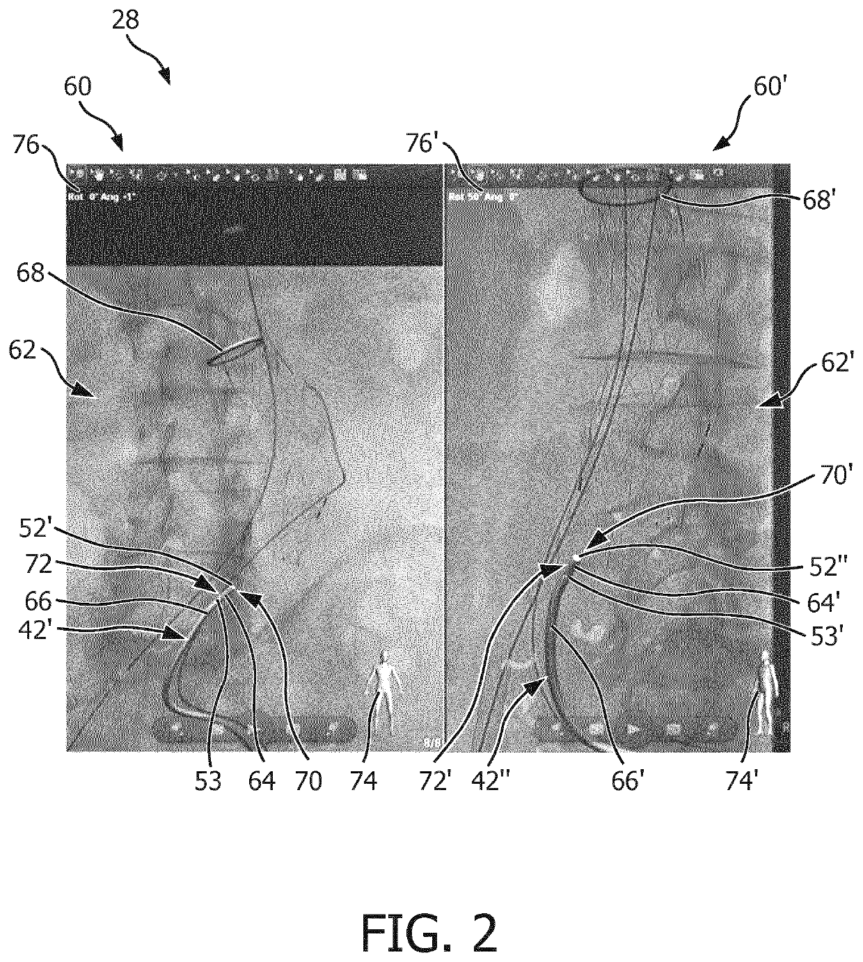
The present invention is about an apparatus for assisting a user in moving an insertion element within an object. It uses a tracking system to track the insertion element and a representation generating system to create an accurate representation of the insertion element within the object. The representation includes at least two different markings along its length, which help the user easily and accurately understand the shape of the insertion element. This improves the user's ability to move the insertion element within the object. Additionally, the invention includes a display that shows the representation with the markings applied, providing a better visualization of the insertion element compared to typical methods. Overall, the invention makes the process of moving an insertion element within an object faster and more accurate.

Problems solved by technology

However, since the x-ray projection image is a two-dimensional (2D) image only, it is difficult for the physician to accurately grasp the three-dimensional (3D) position of the catheter within the inner structure and hence to accurately navigate the catheter tip within the inner structure.

Method used


Image

  • Assisting in moving an insertion element within an object
  • Assisting in moving an insertion element within an object
  • Assisting in moving an insertion element within an object

Examples


Embodiment Construction

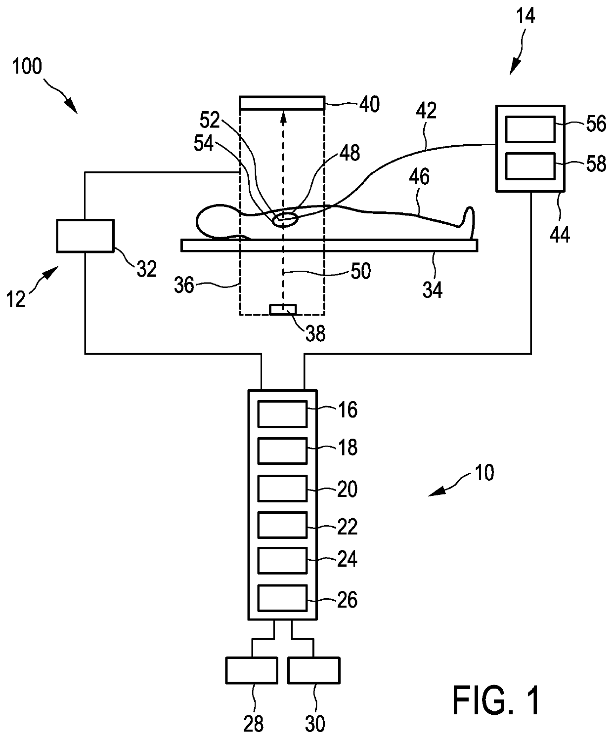
[0050]FIG. 1 shows schematically and exemplarily an embodiment of an interventional system 100 including an assisting apparatus 10, an image acquisition unit 12, and an insertion apparatus 14.

[0051]The assisting apparatus 10 includes an object image providing unit 16, a tracking unit 18, an insertion element representation generating unit 20, a target element providing unit 22, a computer readable medium in form of a memory 24, a transceiver 26, a display 28, and a user interface in form of an input unit 30.

[0052]The image acquisition unit 12 includes a control unit 32, a support means in form of a table 34, a C-arm 36, an x-ray source in form of x-ray tube 38, and x-ray detector 40. The x-ray tube 38 and the x-ray detector 40 are mounted on opposite sides of the C-arm 36, which is movable with respect to the table 34 in order to allow the image acquisition unit 12 to acquire 2D projection images in different acquisition directions. The control unit 32 controls the image acquisition...


PUM


Abstract

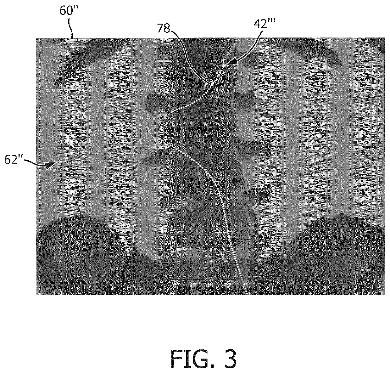
The invention relates to assisting a user in moving an insertion element within an object. A three-dimensional (3D) position and 3D local shape of the insertion element are tracked within the object. Based on the tracked 3D position and 3D local shape of the insertion element, an insertion element representation (42′″) representing the insertion element within the object in its 3D position and 3D local shape is generated. Furthermore at least two different markings (78) applied along the length of the insertion element representation (42′″) representing indications of the local shape of the insertion element are provided. A display image (60″) including the insertion element representation (42′″) with the different markings (78) is displayed. Markings can for example include alternating ring-like structures (78) with alternating lighter and darker colors and / or different colors for the tip and the rest of the insertion element representation for improving 3D visualization of insertion elements.

Description

FIELD OF THE INVENTION[0001]The invention relates to an assisting apparatus for assisting a user in moving an insertion element within an object, a method for assisting a user in moving an insertion element within an object, and a computer program product for assisting a user for moving an insertion element within an object. The invention relates further to an interventional system for moving the insertion element within the object, which comprises the assisting apparatus.BACKGROUND OF THE INVENTION[0002]In catheterization procedures it is important to know the position of a catheter within an inner structure of a person, through which the catheter should be navigated. For this reason generally a realtime x-ray projection image is generated during the catheterization procedure, wherein a physician moves the catheter within the inner structure based on the generated x-ray projection image. However, since the x-ray projection image is a two-dimensional (2D) image only, it is difficult...

Claims


Application Information

Patent Timeline
Patent Type & Authority Applications(United States)
IPC IPC(8): A61B34/20A61B90/00G02B6/02
CPCA61B34/20A61B2034/2061G02B6/02042A61B90/37
Inventor BULLENS, ROLAND WILHELMUS MARIAVAN DEN BOOMEN, WILHELMUS HENRICA GERARDA MARIA
Owner KONINKLJIJKE PHILIPS NV
Learn More