
Apparatus for forward and backward movement of sewing machine

a technology for sewing machines and drives, applied in sewing apparatuses, sewing machine control devices, textiles and paper, etc., can solve the problems of low difficulty in moving the main body to a precise position at high speed, and earlier wear and damage of parts, so as to improve productivity and quality of products, the effect of high speed and precise and smooth movemen

Inactive Publication Date: 2010-09-16
DAE HUNG HITECH +1
View PDF11 Cites 3 Cited by
  • Summary
  • Abstract
  • Description
  • Claims
  • Application Information

AI Technical Summary

Benefits of technology

[0010]The present invention intends to solve above described problems of the conventional devices by providing the main bodies of sewing machines with a forward and backward drive apparatus which enables faster and more accurate movement, improvement of productivity and quality of products, prevent machine parts wear caused by concentrated force or overload, and cost saving.
[0012]The forward and backward drive apparatus using a timing belt for the main body of sewing machine in accordance with this invention provides the advantages including; substantially precise and smooth movement of main body at high speed; improvement of productivity and quality of products; prevention of machine parts damage caused by concentrated force, because the force is distributed by the timing belt; and cost saving by replacing costly screw drive mechanism with timing belt.

Problems solved by technology

In conventional devices that drive main body forward and backward with screw and screw bearing mechanism, it has been difficult to move the main body to precise position at high speed due to relatively higher load.
Such difficulties result in low productivity and quality of products.
In addition, in the conventional devices, driving force is not distributed but concentrated at the screw bearing combined with the screw, leading to earlier wear and damage of the parts.

Method used


Image

  • Apparatus for forward and backward movement of sewing machine
  • Apparatus for forward and backward movement of sewing machine
  • Apparatus for forward and backward movement of sewing machine

Examples


Embodiment Construction

[0020]The functions and their effects of the said members set forth and described hereinabove are described hereinbelow referring to the attached drawings.

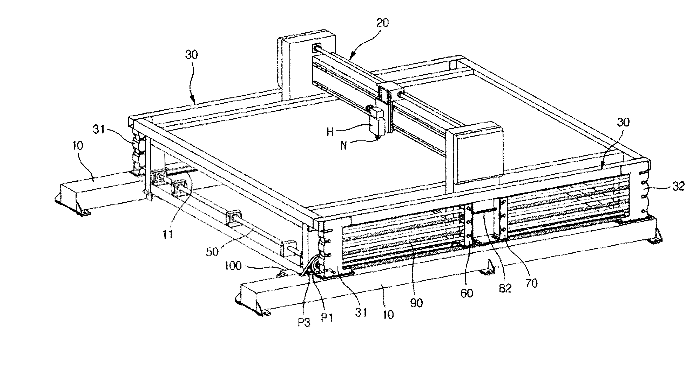
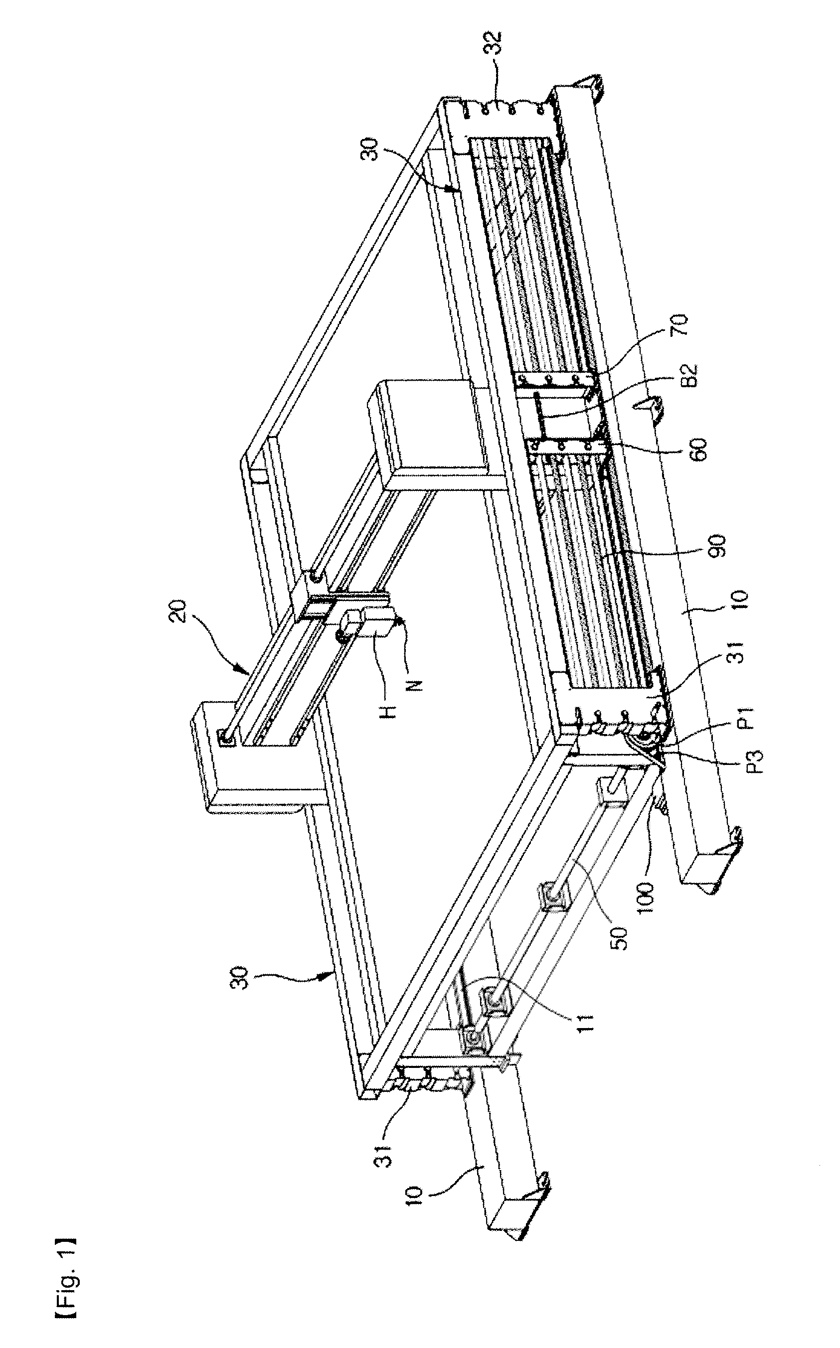
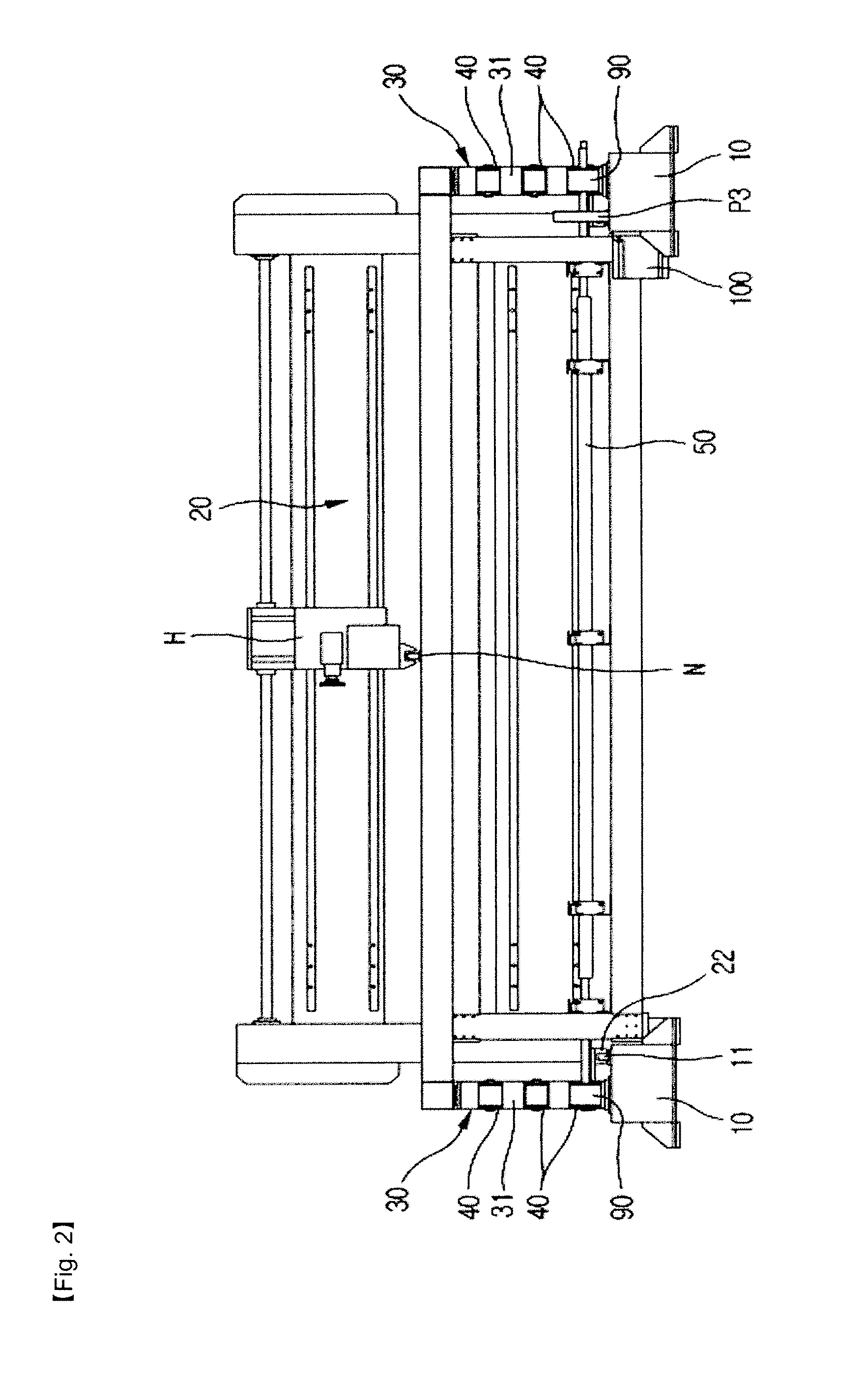
[0021]As illustrated in the FIG. 1 to FIG. 7(c), the forward and backward drive apparatus in accordance with this invention, for the main bodies of the sewing machines comprising a Main Body (20) movable forward and backward and supported on both sides of a Base (10) and Heads (H) movable left and right and supported on the Main Body (20), is technically characterized by being comprised of; a Frame (30) mounted on both top surfaces of the Base (10); the rotatable Timing Gears (40)(41) installed in the front and rear Fixed Frames (31)(32) of the Frame (30) in multiple rows; a Connecting Shat (50) which connects the Timing Gears (40)(41) beneath the Front Fixed Frame (31); the Forward and Backward Movement Frame (60)(70) which is movable forward and backward on the Frame (30) and connected to the Main Body (20); the Rollers (80)(81)...


PUM


Abstract

Forward and backward movement apparatus for main body of sewing machine according to this invention comprises, in sewing machine comprising Main Body movable forward and backward and supported on both sides of a Base and Heads movable left and right and supported on the Main Body; Frame mounted on the Base; Timing Gears installed in the front and rear Fixed Frame of the Frame in multiple rows; Connecting Shat which connects Timing Gears beneath Front Fixed Frame; Forward and Backward Movement Frames is movable forward and backward on the Frame and connected to the Main Body; Rollers are installed in the Forward and Backward Movement Frames in multiple rows to correspond to the Timing Gears; Timing Belt which zigzags through Timing Gear and Roller and Timing Gear and Roller, and both ends of which are connected to the top of Front and Rear Fixed Frames; and electric motor which drives the Connecting Shat in forward and reverse directions.

Description

BACKGROUND OF THE INVENTION[0001]1. Field of the Invention[0002]The present invention relates to a forward and backward drive apparatus of the main body of sewing machine, such as quilting machine, embroidery machine, etc., in particular, a forward and backward drive apparatus of the main body of sewing machine which enables accurate and smooth forward and backward movement of main body at high speed, improvement of productivity and quality, prevent machine parts damage caused by overload, and save operation cost.[0003]2. Background of the Invention[0004]In general, a sewing machine employs a main body movable in forward and backward on a base frame, a needle head movable in left and right on the main body, driving a sewing needle up and down, and a forward and backward drive for the main body.[0005]The forward and backward drive for the main body that drives main body automatically is installed on both sides of the main body to drive the main body forward and backward to bring the ...

Claims


Application Information

Patent Timeline
IPC IPC(8): D05B69/00D05B23/00D05B11/00
CPCD05B11/00D05C15/26D05B69/02D05B23/00
Inventor LEE, KYOO KUNJANG, YONG KYUN
Owner DAE HUNG HITECH
Learn More