Steam-enhanced catalytic cracking of hydrocarbons to produce light olefins

a technology of hydrocarbon cracking and steam-enhanced catalytic cracking, which is applied in the direction of catalytic cracking, hydrocarbon oil treatment, molecular sieve catalysts, etc., can solve the problem of limited use of these cracking methods

Active Publication Date: 2022-03-31
SAUDI ARABIAN OIL CO
View PDF0 Cites 2 Cited by
  • Summary
  • Abstract
  • Description
  • Claims
  • Application Information

AI Technical Summary

Benefits of technology

[0009]The step of separating the hydrocarbon feed to obtain a light hydrocarbon feed and a heavy hydrocarbon feed can be carried out using a cut point temperature between 330° C. and 380° C. The first cracking temperature can be between 630° C. and 750° C. The second cracking temperature can be between 600° C. and 720° C. The light hydrocarbon feed and the heavy hydrocarbon feed can have a residence time in the first downflow FCC reactor and second downflow FCC reactor respectively that is between 0.05 and 10 seconds. The modified catalyst can include between 1 and 20 wt % phosphorus pentoxide (P2O5). According to at least on embodiment, the zeolite can be selected from the group consisting of ZSM-5, zeolite beta, and ultrastable zeolite Y. The modified catalyst can include between 0.5 and 5 wt % metal oxides. The metal oxide can include a metal in a +3 oxidation state. The metal oxide can include a metal selected from the group consisting of iron (III), nickel (III), lanthanum (III), cerium (III), and combinations of the same. The hydrocarbon feed can include a hydrocarbon selected from the group consisting of natural gas condensate and whole crude oil. According to at least one embodiment, the spent FCC catalyst can be gravity-fed to the stripper.

Problems solved by technology

While conventional FCC processes are more energy efficient than steam cracking, their use is typically limited to hydrocarbon feeds having limited amounts of contaminants such as coke, acids, and poisoning metals.

Method used


Image

  • Steam-enhanced catalytic cracking of hydrocarbons to produce light olefins
  • Steam-enhanced catalytic cracking of hydrocarbons to produce light olefins
  • Steam-enhanced catalytic cracking of hydrocarbons to produce light olefins

Examples


example 1

anced Catalytic Cracking of Khuff Gas Condensate

[0058]Khuff gas condensate was processed in three test runs (Test run 1, Test run 2, and Test run 3) using a fixed bed reactor at a temperature of 675° C. Test run 1 was carried out using steam without a catalyst. Test run 2 was carried out using a mixture of 75 wt % commercial equilibrium catalyst (i.e., a mixture of regenerated FCC catalyst and makeup FCC catalyst; referred to as “Ecat”) and 25 wt % modified catalyst. Test run 3 was carried out using steam with a steam-to-feed weight ratio of about 0.5 and the same catalyst mixture used in Test run 2. The modified catalyst was a ZSM-5 catalyst impregnated with metal oxides and about 11.6 wt % phosphorus pentoxide, and sold under the trademark OlefinsUltra®. The modified catalyst contained disodium oxide (Na2O; 0.17 wt %), magnesium oxide (MgO; 0.06 wt %), calcium oxide (CaO; 0.07 wt %), iron(III) oxide (Fe2O3; 0.59 wt %), lanthanum(III) oxide (La2O3; 0.03 wt %), and phosphorus pentox...

example 2

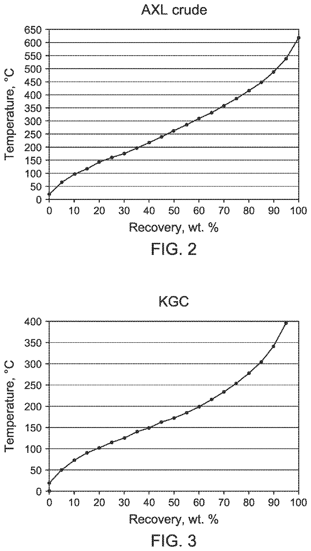
anced Catalytic Cracking of AXL Whole Crude Oil

[0060]Arabian extra light whole crude oil was processed in three test runs (Test run 4, Test run 5, and Test run 6) using a fixed bed reactor at a temperature of about 675° C. Test run 4 was carried out using thermal cracking without a catalyst or steam. Test run 5 was carried out using a mixture of 75 wt % commercial Ecat and 25 wt % modified catalyst. Test run 6 was carried out using steam with a weight ratio of steam to feed of 0.5, and the same catalyst mixture used in Test run 5. The modified catalyst was a ZSM-5 catalyst impregnated with metal oxides and about 11.6 wt % phosphorus pentoxide, and sold under the tradename OlefinsUltra®). The modified catalyst contained disodium oxide (Na2O; 0.17 wt %), magnesium oxide (MgO; 0.06 wt %), calcium oxide (CaO; 0.07 wt %), iron(III) oxide (Fe2O3; 0.59 wt %), lanthanum(III) oxide (La2O3; 0.03 wt %), and phosphorus pentoxide (P2O5; 11.6 wt %). The residence time of the AXL whole crude oil i...

example 3

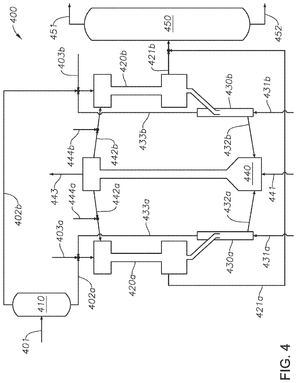
g AXL Whole Crude Oil in a Dual Downflow FCC Reactor Configuration with and without a Modified Catalyst

[0064]Arabian extra light whole crude oil was processed in a dual downflow FCC reactor configuration according to the process shown and described in FIG. 5. The AXL whole crude oil was first separated in a flash drum to obtain a heavy hydrocarbon feed having a boiling temperature range greater than 350° C. and a light hydrocarbon feed having a boiling temperature range less than 350° C. The light and heavy hydrocarbon feeds were preheated and fed to first and second downflow FCC reactors respectively, which were both operated at 675° C. with a steam-to-feed weight ratio of 0.5. Test run 11 was carried out using only Ecat in both reactors. Test run 12 was carried out using a mixture of 75 wt % commercial Ecat and 25 wt % modified catalyst in both reactors. The modified catalyst had the same composition as the modified catalyst used in Example 2.

TABLE 5Yield comparison for steam-enha...


PUM

PropertyMeasurementUnit
mass ratioaaaaaaaaaa
cracking temperatureaaaaaaaaaa

Abstract

A steam-assisted catalytic cracking process for a hydrocarbon feed is provided. The process includes: introducing the hydrocarbon feed, a fluid catalytic cracking (FCC) catalyst, and steam to a FCC reactor with a mass ratio of steam to hydrocarbon feed between 0.05 and 1.0; cracking the hydrocarbon feed in the presence of the FCC catalyst and steam to produce a cracked hydrocarbon feed and spent FCC catalyst, the spent FCC catalyst comprising coke deposits and hydrocarbon deposits; stripping the hydrocarbon deposits from the spent FCC catalyst with steam in a stripper to obtain a hydrocarbon-stripped spent FCC catalyst; regenerating the hydrocarbon-stripped spent FCC catalyst in a regenerator by subjecting the stripped spent FCC catalyst to heat in the presence of oxygen to combust the coke deposits on the stripped spent FCC catalyst and produce a regenerated FCC catalyst; recycling the regenerated FCC catalyst.

Description

BACKGROUND OF THE INVENTION1. Technical Field[0001]The disclosure relates to a process for steam-assisted catalytic cracking of hydrocarbons to obtain light olefin products. More specifically, the disclosure relates to a process for high-severity steam-assisted catalytic cracking of crude oil to obtain light olefin products.2. Discussion of Related Art[0002]Fluid catalytic cracking (FCC) processes available for converting heavy hydrocarbons into light olefins. In conventional FCC systems, a preheated hydrocarbon feed is sprayed into the base of a FCC riser via feed nozzles, where it contacts fluidized catalysts at a temperature in the range of 500-650° C. The hydrocarbon feed is vaporized and its constituent molecules are reacted in the presence of the catalyst to obtain lighter, more valuable compounds such as light petroleum gas, gasoline, and diesel.[0003]In the process of cracking the hydrocarbon feed, coke deposits form on the catalyst and reduce the activity and selectivity of...

Claims


Application Information

Patent Timeline
Patent Type & Authority Applications(United States)
IPC IPC(8): C10G11/18B01J29/46B01J29/90B01J38/06B01J38/16C10G51/06
CPCC10G11/182B01J29/46B01J29/90B01J38/06B01J38/16C10G51/06C10G2300/701C10G2300/708C10G2300/807C10G2300/4006C10G2300/4018C10G2300/4025C10G2400/20C10G11/18B01J8/12B01J8/1881C10G11/05B01J8/26B01J8/388B01J2208/00628B01J29/088B01J29/405
Inventor AKAH, AARONAL-GHRAMI, MUSAED SALEMXU, QI
Owner SAUDI ARABIAN OIL CO
Why Eureka
Try Eureka