Systems and methods for energy storage and recovery using compressed gas

a technology of energy storage and recovery, applied in the field of energy storage, can solve the problems of inadvertent brownout and blackout, natural gas burning, and expensive fuel sources, and achieve the effect of increasing energy density

Inactive Publication Date: 2010-11-16
SUSTAINX
View PDF281 Cites 149 Cited by
  • Summary
  • Abstract
  • Description
  • Claims
  • Application Information

AI Technical Summary

Benefits of technology

[0017]In various embodiments, the invention provides an energy storage system, based upon an open-air hydraulic-pneumatic arrangement, using high-pressure gas in tanks that is expanded in small batches from a high pressure of several hundred atmospheres to atmospheric pressure. The systems may be sized and operated at a rate that allows for near isothermal expansion and compression of the gas. The systems may also be scalable through coupling of additional accumulator circuits and storage tanks as needed. Systems and methods in accordance with the invention may allow for efficient near-isothermal high compression and expansion to / from high pressure of several hundred atmospheres down to atmospheric pressure to provide a much higher energy density.
[0039]The expansion and compression of gas desirably occurs isothermally or nearly isothermally, and this substantially isothermal gas expansion or compression is free of any external heating source other than thermal exchange with the surroundings. The controller can monitor sensor data to ensure isothermal or near-isothermal expansion and compression. The substantially isothermal gas expansion is achieved via heat transfer from outside the first accumulator, the second accumulator, the first intensifier, and the second intensifier therethrough, and to the gas within each accumulator pneumatic side and intensifier pneumatic side. Staged expansion and compression, using accumulators and one or more intensifiers in a circuit to expand / compress the gas more evenly, at varied pressures also helps to ensure that a fluid pressure range at which the motor / pump operates efficiently and most optimally is continuously provided to or from the motor / pump.

Problems solved by technology

In certain parts of the United States, inability to meet peak demand has led to inadvertent brownouts and blackouts due to system overload and deliberate “rolling blackouts” of non-essential customers to shunt the excess demand.
However, these units burn expensive fuel sources, such as natural gas, and have high generation costs when compared with coal-fired systems, and other large-scale generators.
Accordingly, supplemental sources have economic drawbacks and, in any case, can provide only a partial solution in a growing region and economy.
The most obvious solution involves construction of new power plants, which is expensive and has environmental side effects.
In addition, because most power plants operate most efficiently when generating a relatively continuous output, the difference between peak and off-peak demand often leads to wasteful practices during off-peak periods, such as over-lighting of outdoor areas, as power is sold at a lower rate off peak.
The array may generate well for a few hours during the day, but is nonfunctional during the remaining hours of low light or darkness.
However, such generators are often costly, use expensive fuels, such as natural gas or diesel fuel, and are environmentally damaging due to their inherent noise and emissions.
The flywheel units are expensive to manufacture and install, however, and require a degree of costly maintenance on a regular basis.
Many large-scale batteries use a lead electrode and acid electrolyte, however, and these components are environmentally hazardous.
Batteries must often be arrayed to store substantial power, and the individual batteries may have a relatively short life (3-7 years is typical).
Thus, to maintain a battery storage system, a large number of heavy, hazardous battery units must be replaced on a regular basis and these old batteries must be recycled or otherwise properly disposed of.
However, a large array of such capacitors is needed to store substantial electric power.
Ultracapacitors, while more environmentally friendly and longer lived than batteries, are substantially more expensive, and still require periodic replacement due to the breakdown of internal dielectrics, etc.
The main drawback of CAES is probably the geological structure reliance, which substantially limits the usability of this storage method.
In addition, CAES power plants are not emission-free, as the pre-compressed air is heated up with a fossil fuel burner before expansion.
Moreover, [CAES plants] are limited with respect to their effectiveness because of the loss of the compression heat through the inter-coolers, which must be compensated during expansion by fuel burning.
The fact that conventional CAES still rely on fossil fuel consumption makes it difficult to evaluate its energy round-trip efficiency and to compare it to conventional fuel-free storage technologies.”
In general, the use of highly compressed gas as a working fluid for the motor poses a number of challenges due to the tendency for leakage around seals at higher pressures, as well as the thermal losses encountered in rapid expansion.
While heat exchange solutions can deal with some of these problems, efficiencies are still compromised by the need to heat compressed gas prior to expansion from high pressure to atmospheric pressure.
This system has limitations in that its energy density is low.
That is, the amount of compression possible is limited by the size of the tank space.
In addition, since the gas does not completely decompress when the fluid is removed, there is still additional energy in the system that cannot be tapped.
To make a closed air system desirable for large-scale energy storage, many large accumulator tanks would be needed, increasing the overall cost to implement the system and requiring more land to do so.
This can result in problematic gas leakage, as it is quite difficult to completely seal a moving, high-pressure piston against gas leakage.
In addition, the '311 patent proposes a complex, difficult to manufacture and maintain accumulator structure that may be impractical for a field implementation.
This complex structure adds expense and potentially compromises the gas and fluid seals of the system.

Method used


Image

  • Systems and methods for energy storage and recovery using compressed gas
  • Systems and methods for energy storage and recovery using compressed gas
  • Systems and methods for energy storage and recovery using compressed gas

Examples


Embodiment Construction

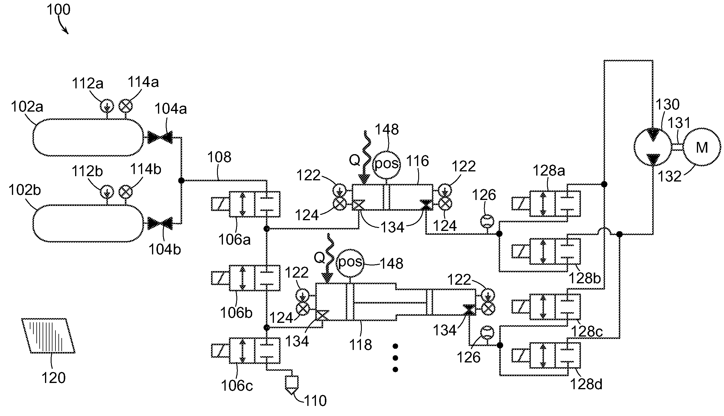
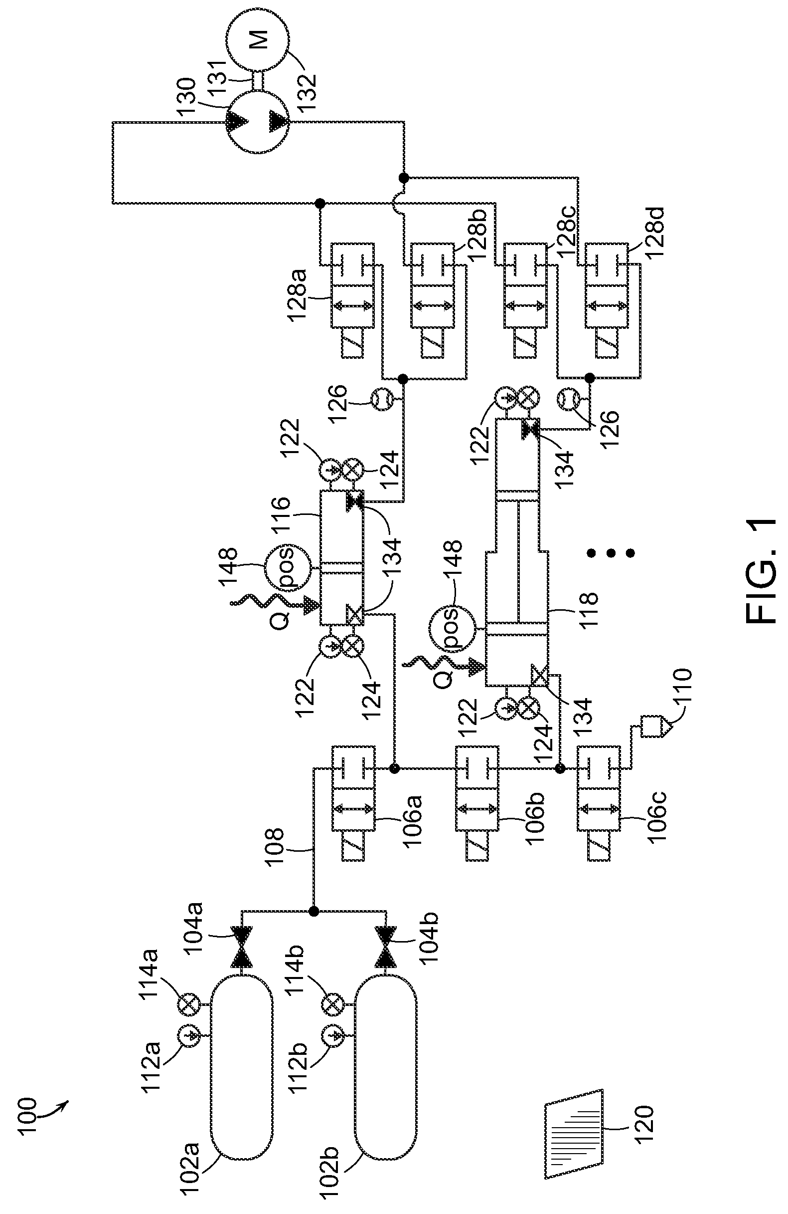
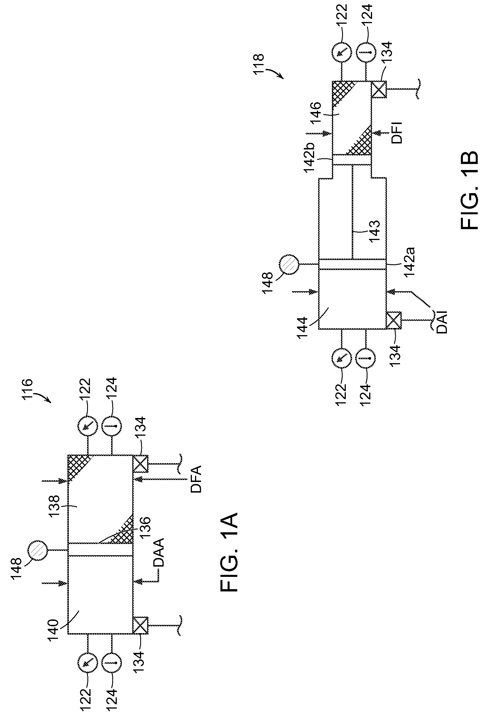
[0063]In the following, various embodiments of the present invention are generally described with reference to a single accumulator and a single intensifier or an arrangement with two accumulators and two intensifiers and simplified valve arrangements. It is, however, to be understood that the present invention can include any number and combination of accumulators, intensifiers, and valve arrangements. In addition, any dimensional values given are exemplary only, as the systems according to the invention are scalable and customizable to suit a particular application. Furthermore, the terms pneumatic, gas, and air are used interchangeably and the terms hydraulic and fluid are also used interchangeably.

[0064]FIG. 1 depicts one embodiment of an open-air hydraulic-pneumatic energy storage and recovery system 100 in accordance with the invention in a neutral state (i.e., all of the valves are closed and energy is neither being stored nor recovered. The system 100 includes one or more hi...


PUM


Abstract

The invention relates to methods and systems for the storage and recovery of energy using open-air hydraulic-pneumatic accumulator and intensifier arrangements that combine at least one accumulator and at least one intensifier in communication with a high-pressure gas storage reservoir on a gas-side of the circuits and a combination fluid motor / pump, coupled to a combination electric generator / motor on the fluid side of the circuits.

Description

CROSS-REFERENCE TO RELATED APPLICATIONS[0001]This application claims priority to U.S. Provisional Patent Application Ser. Nos. 61 / 043,630, filed on Apr. 9, 2008, and 61 / 148,091, filed on Jan. 30, 2009, the disclosures of which are hereby incorporated herein by reference in their entireties.STATEMENT REGARDING FEDERALLY SPONSORED RESEARCH[0002]This invention was made with government support under IIP-0810590 awarded by the NSF. The government has certain rights in the invention.FIELD OF THE INVENTION[0003]The invention relates to energy storage, and more particularly, to systems that store and recover electrical energy using compressed fluids.BACKGROUND OF THE INVENTION[0004]As the world's demand for electric energy increases, the existing power grid is being taxed beyond its ability to serve this demand continuously. In certain parts of the United States, inability to meet peak demand has led to inadvertent brownouts and blackouts due to system overload and deliberate “rolling black...

Claims


Application Information

Patent Timeline
Patent Type & Authority Patents(United States)
IPC IPC(8): F04B49/00F15B1/02
CPCF15B1/024F15B11/032F15B21/08F15B2211/20569F15B2211/212F15B2211/214F15B2211/216F15B2211/30505F15B2211/3057F15B2211/30575F15B2211/3058F15B2211/3111F15B2211/31594F15B2211/327F15B2211/40515F15B2211/41509F15B2211/41554F15B2211/426F15B2211/45F15B2211/50581F15B2211/5153F15B2211/62F15B2211/6309F15B2211/7058
Inventor MCBRIDE, TROY O.BOLLINGER, BENJAMIN R.
Owner SUSTAINX
Why Eureka
Try Eureka