Image-Guided Surgery System

a surgical system and imageguide technology, applied in the field of surgical procedures, can solve the problems of inability to accurately understand the surgical field provided by medical imaging modalities to the surgeon, difficulty in accurately understanding the surgical field, and insufficient precision of the precise location of the system, so as to reduce computation time and reduce the volume of the imaged area

Pending Publication Date: 2022-04-07
THE BOARD OF TRUSTEES OF THE UNIV OF ILLINOIS
View PDF0 Cites 2 Cited by
  • Summary
  • Abstract
  • Description
  • Claims
  • Application Information

AI Technical Summary

Benefits of technology

[0018]To further inform the analysis and reduce computation time, additional retina layer or other tissue anatomical information including a loop for informing the feedback loop with distinction parameters between clinically relevant tissue boundaries among anatomical structures, can be provided wherein the loop can be informed regarding the distinction parameters from a learned or stored information database, and/or form additional imaging information obtained from imaging data updates obtained and/or received at an earlier time.
[0019]In accordance with the principles her...

Problems solved by technology

However, one difficulty encountered during such procedures is that it can be difficult to accurately understand the visualization of the surgical field provided by medical imaging modalities to the surgeon.
For example, diagnostic medical ultrasound provides a two-dimensional image of a space and may show various tissue densities as well as surgical instruments present in the surgical field, but it may nevertheless be difficult for the surgeon to visualize or understand the exact location, in three dimensions, of the surgical instrument(s) relative to various tissues displayed in the surgical field.
Unfortunately, such systems lack needed precision regarding the precise location of the instrument, are adversely affected by imaging artifacts (such as shadows) induced by the material properties of surgical instruments, and do not provide any feedback or guidance to the surgeon or instrumentation.
Further, delays in the visual output arise due to computational complexities, so the surgeon may not be visualizing the surgical f...

Method used


Image

  • Image-Guided Surgery System
  • Image-Guided Surgery System
  • Image-Guided Surgery System

Examples


Embodiment Construction

[0047]As used herein the term “real-time” refers to the acquisition, processing, and output of images and data that can be used to inform surgical tactics and / or modulate instruments and / or surgical devices during a surgical procedure.

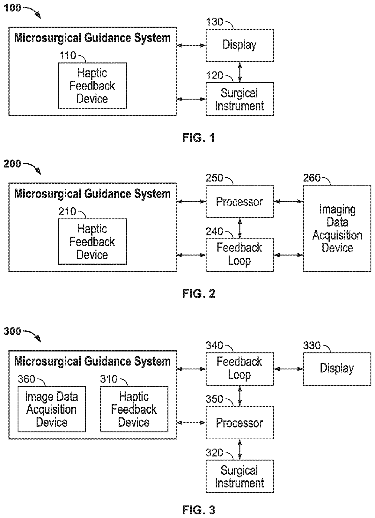
[0048]As described above, during various surgical procedures, unintended interactions between surgical instruments and tissue within the surgical field may have unintended consequences, some of which may be permanent. Ophthalmic microsurgery, for example, entails the use of mechanical and motorized instruments to manipulate delicate intraocular tissues. Great care must be afforded to tissue-instrument interactions, as damage to delicate intraocular structures such as the neurosensory retina, optic nerve, lens capsule, and corneal endothelium can result in significant visual morbidity. The surgical guidance system described herein provides a feedback loop whereby the location of a surgical instrument in relation to delicate tissues (e.g., ocular tissues...


PUM


Abstract

An image-guided surgical system includes a processor, a display communicatively coupled to the processor, and an imaging system communicatively coupled to the processor. A memory device, communicatively coupled to the processor, stores instructions, executable by the processor, to cause the processor to receive, from the imaging system, real-time image data of an ophthalmological surgical field during an ophthalmological surgical procedure, and analyze the image data in real-time to identify an ocular tissue boundary present in the image data of the ophthalmological surgical field. The instructions cause the processor to provide real-time visual, auditory, and/or haptic feedback in response to the identified ocular tissue boundary.

Description

CROSS-REFERENCE TO RELATED APPLICATIONS[0001]This application claims priority under 35 U.S.C. §. 119(e) to U.S. Provisional Patent Application No. 62 / 803,418, filed Feb. 8, 2019, and entitled “Image Guided Microsurgery System,” the contents of which are hereby incorporated by reference herein, in their entirety and for all purposes.TECHNOLOGICAL FIELD[0002]The present disclosure relates to assistive systems for surgical procedures and, in particular, to image-guided surgical systems that provide real-time feedback to surgeons during a surgical procedure.BACKGROUND[0003]Surgical procedures include inherent risk to the patient, the mitigation of which is an area of constant research and development. One advance in the field of medical practice has been the move away from open surgery, in which the surgical patient is opened up to expose relatively large areas of the patient's inner cavities, and towards minimally invasive surgeries. Minimally invasive surgeries do not require large in...

Claims


Application Information

Patent Timeline
IPC IPC(8): A61B34/20A61B34/00A61B90/20A61F9/007G06T7/11
CPCA61B34/20A61B34/72A61B34/76A61B2090/365A61F9/00736G06T7/11A61B2034/2065A61B90/20A61F9/007A61B34/25G06T2210/41A61B2017/00115A61B2090/3735A61B2017/00119A61B2090/502A61B90/03A61B2090/061G06T7/12G06T2207/30041G06T2207/10021A61B1/000094A61B1/000095A61B1/000096G06T2207/10101G06T2207/20132
Inventor LEIDERMAN, YANNEK I.LUCIANO, CRISTIAN J.
Owner THE BOARD OF TRUSTEES OF THE UNIV OF ILLINOIS
Why Eureka
Try Eureka