An adjustable light source holder, a directable spotlight and a manufacture method thereof

a technology of light source holder and directable spotlight, which is applied in the direction of lighting device details, lighting support devices, lighting and heating apparatus, etc., can solve the problems of cumbersome and complicated redirection of spotlights, and achieve the effect of rapid prototyping and low cos

Active Publication Date: 2022-04-07
SIGNIFY HLDG BV
View PDF0 Cites 0 Cited by
  • Summary
  • Abstract
  • Description
  • Claims
  • Application Information

AI Technical Summary

Benefits of technology

[0017]Fused deposition modeling (FDM) is a widely used additive manufacturing technology. FDM is commonly used for modeling, prototyping, and production applications. FDM works on an additive principle by laying down material in layers; a plastic filament or metal wire is unwound from a coil and supplies material to produce a part. Possibly, (for thermoplastics for example) the filament is melted and extruded before being laid down. FDM is a rapid prototyping technology. Other terms for FDM are fused filament fabrication (FFF) or filament 3D printing (FDP), which are considered to be equivalent to FDM. In general, FDM printers use a thermoplastic filament, which is heated to its melting point and then extended, layer by layer, (or in fact filament after filament) to create a three-dimensional object. FDM printers are relatively fast, low cost and can be used for printing complicated 3D objects. Such printers are used in printing various parts and shapes using various polymers for a wide range of applications.
[0018]The concurrent FDM may be performed such that the inner part cannot be disassembled from the outer part. This may lead to a better fit of the inner part inside the outer part. Furthermore, elastically expanding or deforming details may no longer be necessary if disassembly is regarded as a redundant functionality.

Problems solved by technology

Using screws however, necessitates additional parts to a spotlight system, making it more complex, as well as rendering redirecting of the spotlight cumbersome and complicated.

Method used


Image

  • An adjustable light source holder, a directable spotlight and a manufacture method thereof
  • An adjustable light source holder, a directable spotlight and a manufacture method thereof
  • An adjustable light source holder, a directable spotlight and a manufacture method thereof

Examples


Embodiment Construction

[0037]The present invention will now be described more fully hereinafter with reference to the accompanying drawings, in which currently preferred embodiments of the invention are shown. This invention may, however, be embodied in many different forms and should not be construed as limited to the embodiments set forth herein; rather, these embodiments are provided for thoroughness and completeness, and fully convey the scope of the invention to the skilled person.

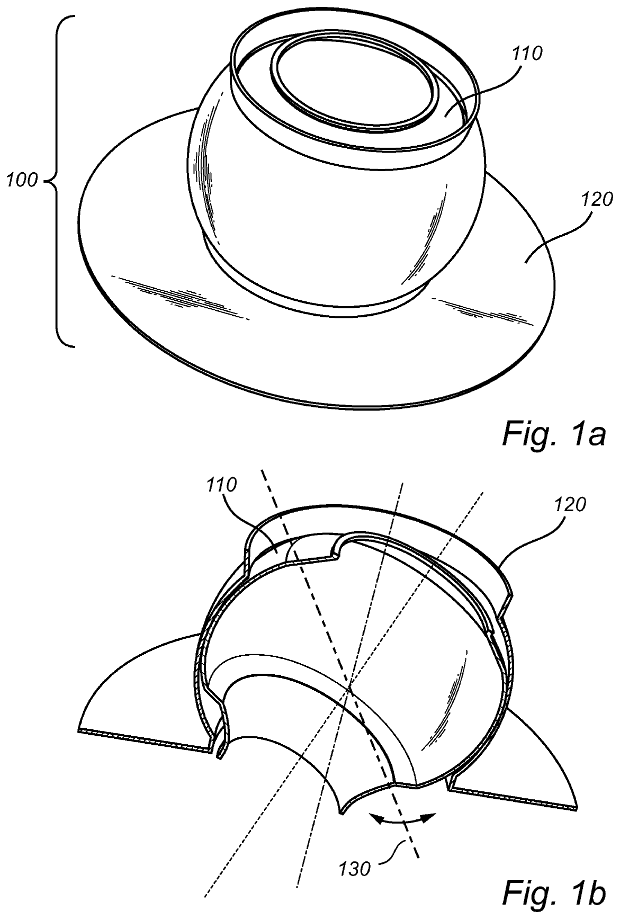
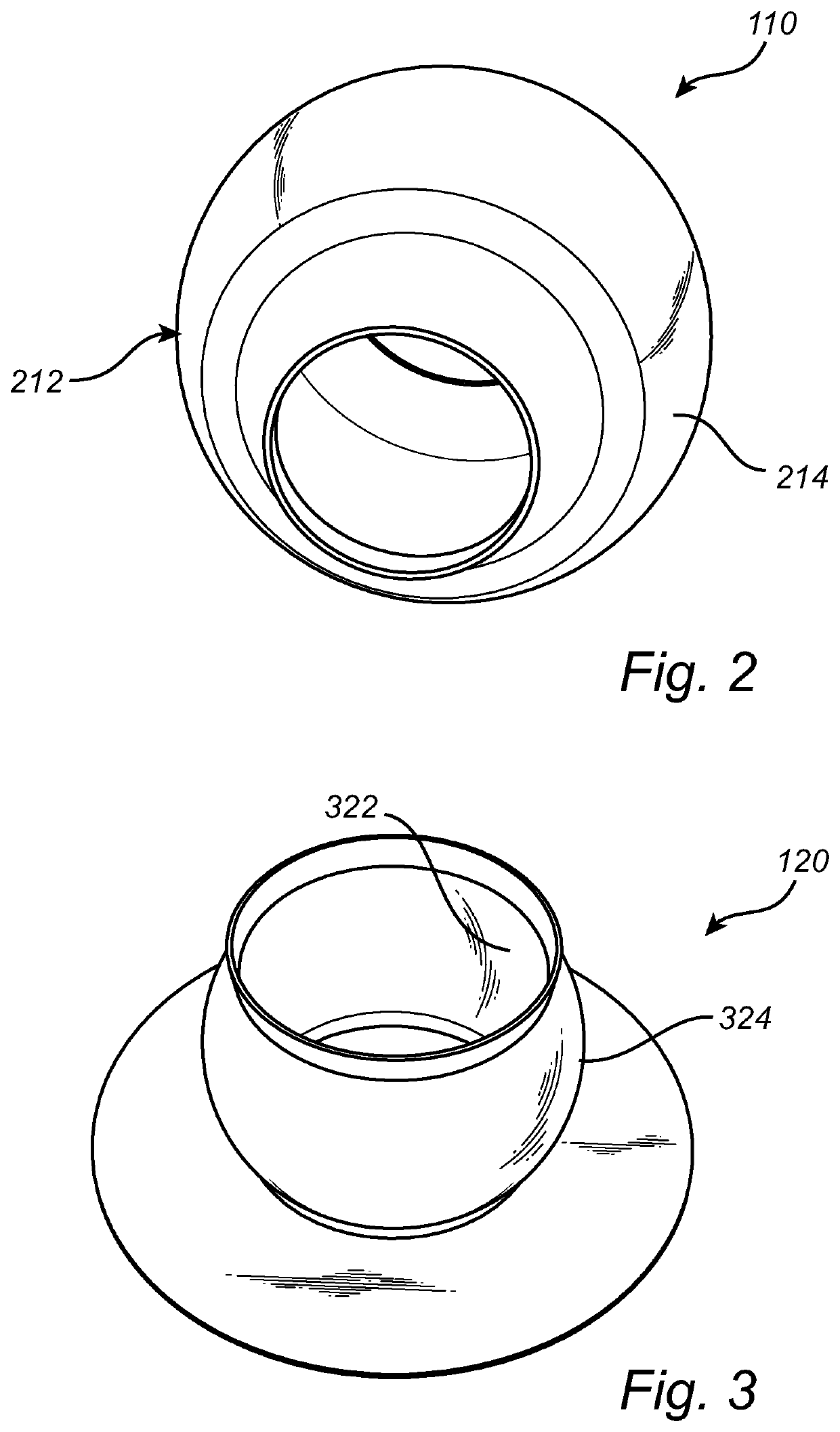
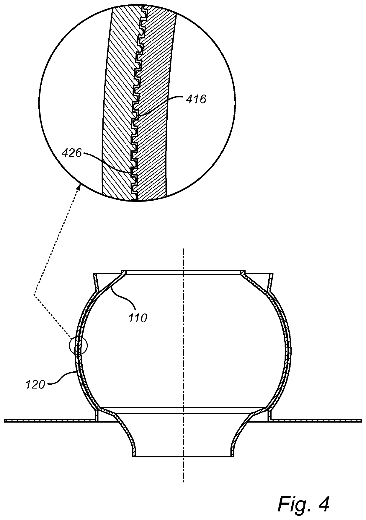
[0038]In FIG. 1a, an adjustable light source holder 100 is illustrated which comprises an inner part 110 and an outer part 120. The inner part 110 is configured to house a light source like for example a LED light source for general lighting applications. Furthermore, the inner part 110 itself is housed within a cavity of the outer part 120 which allows the inner part 110 to be tiltable relative to the outer part 120 about an arbitrary tilt axis 130, as is illustrated in FIG. 1b. The inner part 110 may be directed in a vari...


PUM


Abstract

The present invention relates to an adjustable light source holder (100), comprising an inner part (110), in the form of a partly spherical shell (214), configured to house a light source; an outer part (120), in the form of a partly spherical shell (324), configured to house and interact with the partly spherical shell of the inner part; wherein the inner part is tiltable relative to the outer part about an arbitrary tilt axis (130); wherein the inner part (110) is made from an elastic material; and wherein an outer surface (212) of the inner part and/or an inner surface (322) of the outer part comprises a rough portion (416, 426). Methods of manufacturing the adjustable light source holder and related directable spotlight systems are also presented.

Description

FIELD OF THE INVENTION[0001]The present inventive concept relates to an adjustable light source holder intended for directable spotlights in general lighting applications.BACKGROUND OF THE INVENTION[0002]Directable, general lighting, spotlights are available on the market today, for domestic or other use environments and may be found in for example ceilings, walls and furniture. Typically, these spotlights are configured by affixing a light source using screws, or similar fixing means, to achieve a desired directional illumination profile of the spotlight. Using screws however, necessitates additional parts to a spotlight system, making it more complex, as well as rendering redirecting of the spotlight cumbersome and complicated. With these issues in consideration, it is clear that there is room for improvement within the technical field.[0003]U.S. Pat. No. 6,019,477 discloses an emergency lighting unit. The unit has a housing with a circular opening, a mounting ring that fits withi...

Claims


Application Information

Patent Timeline
Patent Type & Authority Applications(United States)
IPC IPC(8): F21V21/30
CPCF21V21/30
Inventor HIKMET, RIFAT ATA MUSTAFAWOUTERS, HUIBERTVAN BOMMEL, TIES
Owner SIGNIFY HLDG BV
Why Eureka
Try Eureka