A drawer sliding system

Pending Publication Date: 2022-04-21
IKEA SUPPLY
6 Cites 0 Cited by

AI-Extracted Technical Summary

Problems solved by technology

A common problem with existing solutions is that they are often space consuming, in that they take up relatively large space on the drawer and/or on the supporting structure.
While this often provides benefits in the load capacity of the drawer, this ma...

Method used

[0041]The drawer member 200 is preferably made in one piece out of plastic, and the sliding engagement with the rail 300 is preferably a low-friction system such as described in previous patent application WO2017/044032 A1, which is incorporated herein by reference. The rail 300 and/or the drawer member 200 may at least partially be coated with a lacquer comprising a resin, wherein said lacquer in turn is at least partly coated with a lipophilic composition coating to provide a sliding surface/contact surface with a lowered friction. Examples of such surface treatments are disclosed in WO2017/044032 A1.
[0049]The rail engagement portion 202 length along with the length of the rail 300 defines the distance which the drawer member 200 can be moved in relation to the rail 300, and thus also the distance the drawer 500 can be moved in relation to the support 600. Preferably, the length of the rail 300 is kept as short as possible to save material and costs. Consequently, the rail 300 should essentially correspond to the length of the side panel 502 of the drawer 500 or only be slightly longer, such that the rail 300 does not excessively extend rearward of the drawer 500 when the drawer 500 is closed.
[0054]The second attachment member 208 is less likely to be subjected to such high vertical forces in the direction of the rail 300, and can consequently be arranged closer to the rail engagement portion 202. The varying distance from the rail engagement portion 202 of the first and second drawer attachment members 206, 208 further brings the beneficial effect of reducing or to some extent optimizing the amount of material required for manufacturing each drawer member 200.
[0063]In one embodiment, the material of the rail engagement portion 202 between the contact surfaces 212 on the respective ends 220, 222 of the drawer member 200 is omitted. This forms a rail engagement portion 202 that is discontinuous, and in which the tracks 214 are only present at the front end 220 and the rear end 222 of the drawer member 200. The material nee...

Benefits of technology

[0013]In one embodiment, the drawer member is attachable to a side surface of a drawer side panel by means of the first attachment member and the second attachment member receivable in corresponding openings in the side wall. The first attachment member is arranged on the drawer member farther away from a rear end of a drawer engagement portion and farther away from a rail engagement portion than the second attachment member. The first attachment member is thus arranged forward of the second attachment member, and will be subjected to higher loads as a result. By placing it farther away from the rail engagement portion and thus also from the rail, which are both preferably parallel with the upper edge of the side panel, is the amount of...

Abstract

A drawer sliding system (100) for a drawer (500), comprising a drawer member (200) mountable to the drawer (500) and a rail (300) fixedly mountable to an associated support (600) of a furniture (1000), the drawer member (200) comprises at least one contact surface (212), wherein the drawer member (200) is arranged to be moveable relative to the rail (300), wherein the contact surface (212) and the rail (300) are adapted for together forming a sliding connection between the drawer (500) and the associated support (600) such that the drawer (500) and the drawer member (200) are moveable in relation to the support (600) along the rail (300), wherein at least one drawer sliding system (100) attaches each drawer (500) to the support (600).

Application Domain

Technology Topic

Image

  • A drawer sliding system
  • A drawer sliding system
  • A drawer sliding system

Examples

  • Experimental program(1)

Example

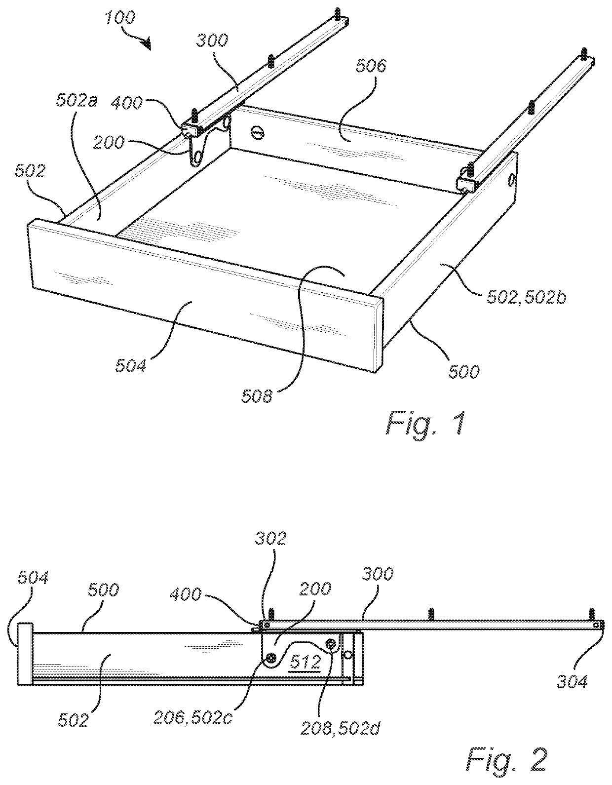
[0036]The disclosed embodiments will now be described more fully hereinafter with reference to the accompanying drawings, in which certain embodiments of the invention are shown. Like numbers refer to like elements throughout. Throughout the application is reference made to directions, such as forward, rearward etc. A forward direction in the context of this application is the direction in which the drawer 500, and all thereto attached components, moves during an opening motion. Consequently, the rearward direction is opposite the forward and thus the direction of a closing motion of the drawer 500.
[0037]FIG. 1 shows a drawer 500 comprising a drawer sliding system 100. The drawer 500 preferably comprises a front panel 504, two side panels 502, a rear panel 506 and a bottom panel 508. Typically, drawer panels are made to a large extent from wood based materials such as particle board, fibre board or solid wood. The teachings herein are however not limited to use only with furniture of wood based materials but could just as well be used with for instance aluminium furniture or stainless steel furniture.
[0038]In a preferred embodiment is one sliding system 100 mounted to each side panel 502 of the drawer 500, but it is also feasible that a single drawer sliding system 100 alone supports each drawer 500. The sliding system 100 is intended to be mounted to the drawer 500 and to a supporting structure 600 (shown in FIG. 8), thus supporting the drawer 500 such that it can be moved in relation to the support 600. Preferably is a rail 300 of the sliding system 100 configured to be attached to a downward facing surface 602 of the support 600 such that the drawer 500 is supported in a hanging manner by the cooperation of the drawer member 200 and the rail 300 of each sliding system 100. However, it is also possible that the rails 300 are mounted to vertical surfaces, inclined surfaces, or to an upward facing horizontal surface.
[0039]The rail 300 has an elongated shape and is configured to be mounted to the support 600 by means of a plurality of fasteners such as screws or snap-lock fasteners etc. The rail 100 is preferably made of metal, such as aluminium or steel.
[0040]The drawer member 200 is configured to be mounted to the rear portion 512 of the drawer 500, each drawer member 200 being in sliding engagement with a respective rail 300.
[0041]The drawer member 200 is preferably made in one piece out of plastic, and the sliding engagement with the rail 300 is preferably a low-friction system such as described in previous patent application WO2017/044032 A1, which is incorporated herein by reference. The rail 300 and/or the drawer member 200 may at least partially be coated with a lacquer comprising a resin, wherein said lacquer in turn is at least partly coated with a lipophilic composition coating to provide a sliding surface/contact surface with a lowered friction. Examples of such surface treatments are disclosed in WO2017/044032 A1.
[0042]The drawer member 200 moves with the drawer 500 and guides this motion by its interaction with the rail 300. In FIG. 1 and FIG. 2, the drawer 500 is seen in an open position where the drawer members 200 are arranged close to the front end 302 of the respective rail 300. Each rail 300 may be fitted with a stopper member 400 mounted to the front end 302. The stopper member 400 may limit the motion of the drawer member 200 in each rail 300 by its interaction with the front panel 504 and/or the drawer member 200. The stopper member 400 will be described in further detail in relation to FIGS. 6 and 7.
[0043]What can be further seen in the preferred embodiment shown in FIGS. 1 and 2 is that the drawer members 200, while only being mounted to the rear portion of the drawer 500 and having an extension being signicantly less than the length of the side panel 502 thereof, preferably supports the full weight of the drawer 500 when the drawer 500 is open. The drawer member 200 comprises at least one contact surface 212, and is via at least one contact surface 212 arranged to be in sliding contact with the rail 300 during the entire sliding movement of the drawer 500. As will further elaborated on below, the drawer member 200 may comprise a plurality of contact surfaces 212. It not necessary that all of these are in contact with the rail 300 at all times during the sliding motion, as this varies depending on the load of the drawer 500 etc.
[0044]A force from gravity, i.e. the entire or a part of the weight of the drawer 500, excerted on the rail 300 by the at least one contact surface 212 is however essentially constant during the entire sliding movement of the drawer 500. The entire sliding movement comprises any position of the drawer at least when the drawer is not in or adjacent to its closed position relative the rail.
[0045]While it is preferred that each sliding system 100 comprises one drawer member 200 attachable to the side of the drawer 500, it is also envisoned that each sliding system 100 may comprise more than one drawer member 200, thus distributing the load from the drawer 500 through more drawer members 200 to the rail 300. The force from gravity excerted on the rail 300 by the drawer members 200 of each sliding system 100 would still be essentially constant during the sliding motion of the drawer 500, as the drawer members 200 are fixed to and thus moves with the drawer 500.
[0046]The drawer 500 may be connected to the rail 300 only via the drawer member 200 of each drawer sliding system 100 at least when the drawer 500 is not in or adjacent to its closed position relative the rail 300, i.e. during the entire sliding movement of the drawer500. This is beneficial as many conventional drawer guiding systems rely on an additional support member mounted to a forward portion of for instance a cabinet. The sliding system 100 herein removes the need for such a support member, thus achieving a constant force on the rail 300 from the drawer member 200 during the sliding motion of the drawer 500.
[0047]Consequently, and as the drawer member 200 is mounted to a rear portion 512 of the drawer 500, the drawer member 200 of each sliding system 100 needs not only to able to withstand a vertical load, but also to be able to transfer a rotational force that may arise due to the center of gravity of the drawer 500 possibly being located forward of where the drawer members 200 are attached to the respective rail 300.
[0048]FIG. 3 shows a side view of the drawer member 200 as it is about to be mounted to the rail 300. The drawer member 200 may comprise a rail engagement portion 202 which is the portion of the drawer member 200 that connects to the rail 600. The length of the rail engagement portion 202 along with the contact surfaces 212 arranged thereon allows it to not only absorb vertical and lateral forces, but also withstand the rotational forces mentioned above.
[0049]The rail engagement portion 202 length along with the length of the rail 300 defines the distance which the drawer member 200 can be moved in relation to the rail 300, and thus also the distance the drawer 500 can be moved in relation to the support 600. Preferably, the length of the rail 300 is kept as short as possible to save material and costs. Consequently, the rail 300 should essentially correspond to the length of the side panel 502 of the drawer 500 or only be slightly longer, such that the rail 300 does not excessively extend rearward of the drawer 500 when the drawer 500 is closed.
[0050]The drawer member 200 may further comprise a first and a second attachment member 206, 208 attachable to the drawer 500. The attachment members 206, 208 are preferably in the shape of press-lock connectors having circumferential external ribs that will secure the drawer member 200 to the drawer 500. The attachment members 206, 208 may further be expandable by the introduction of for instance a screw or similar in the central opening in each member 206, 208, upon which the four sections into which each attachment member 206, 208 is divided will be pushed apart and against the material of the drawer 500.
[0051]The first attachment member 206 and the second attachment member 208 are receivable in corresponding openings 502c, 502d in the drawer 500, preferably in each side wall 502 thereof. Even more preferred, the openings are arranged in an inwards facing surface 502a (shown in FIG. 1) of each side panel 502.
[0052]The first attachment member 206 is arranged on the drawer member farther away from a rear end 224 of the drawer engagement portion 204 and farther away from the rail engagement portion 202 than the second attachment member 208. In other words, the attachment members 206, 208 are arranged such that when the drawer member 200 is mounted to the rail 300, the first attachment member 206 is arranged farther away from a rear end 506 of the rail 300 and farther away from the rail engagement portion 202 than the second attachment member 208.
[0053]It is the first attachment member 206 that will be subjected to the largest load from the drawer 500, as it is arranged forward of the second attachment member 208. With the drawer member 200 attached to a side surface 502a, 502b of the side panel 502 will the first attachment member 206, in most load cases, subject the side panel 502 with a reaction force directed towards the rail 300. Depending on the material used in the side panel 502, the side panel 502 itself may be the critical component in terms of the amount of load that the drawer 500 can be subjected to. By arranging the first attachment member 208 at a larger distance from the rail attachment member 202 is the amount of drawer side wall 502 material that absorbs forces from the first attachment member 206 increased.
[0054]The second attachment member 208 is less likely to be subjected to such high vertical forces in the direction of the rail 300, and can consequently be arranged closer to the rail engagement portion 202. The varying distance from the rail engagement portion 202 of the first and second drawer attachment members 206, 208 further brings the beneficial effect of reducing or to some extent optimizing the amount of material required for manufacturing each drawer member 200.
[0055]Preferably is each drawer attachment member 206, 208 protruding from a wall 210 extending from the rail engagement portion 202. The wall 210 is configured to be arranged parallel with the side wall 502 of the drawer 500 when the drawer member 200 is attached thereto. The wall 210 and the drawer attachment members 206, 208 together forms the drawer engagement portion 204 of the drawer member 200, i.e. the portion 204 of the drawer member 200 being configured to form the attachment to the drawer 500.
[0056]It is to be realized that while the wall 210 is shown as a single common wall to which both attachment members 206, 208 are attached, the wall 210 may also be divided in two separate walls each comprising one of the attachment members 206, 208.
[0057]The wall 210 is preferably arranged aligned with a center axis A, a centerline, through the drawer member 200. This is beneficial in terms of the load capacity and structural integrity of the drawer member 200.
[0058]However, it is also envisioned that the wall may be offset from the center axis A in the direction opposite the protrusion of the first attachment member 206 and the second attachment member 208. The rail engagement portion 202 of the drawer member 200, and also the rail 300, will consequently be arranged at least partially above the side wall 502 of the associated drawer 500. This is beneficial in that it gives the drawer 500 and the associated sliding system(s) 100 an integrated appearance.
[0059]Further still, the distance L defined between the front end 220 of the rail engagement portion 220 and a rear end 224 of the drawer engagement portion 204 defines the maximum extraction of the drawer 500 in relation to the rail 300. The distance L should be less than half the length of the drawer side panel 502, preferably approximately ¼ of the length thereof. The distance L essentially corresponds to the portion of the drawer side panel 502, or the drawer 500 as a whole, that cannot be extended outside of the front end 302 of the rail 300.
[0060]The drawer member 200 should preferably be mounted to the drawer 500 such that the rear end 224 is as close as possible to the rear panel 506, while the front end 220 will limit the movement of the drawer member 200 in relation to the rail 300 by its contact with the stopper member 400.
[0061]With a reduction in the distance L will the drawer member 200 and the associated drawer 500 be able to be extracted, or opened, further in relation to the rail 300. However, the drawer member 200 and the rail 300 will consequently also be excerted to higher rotational forces for a given weight of the drawer 500 as the distance from the first attachment member 206, which is attached to the wall 210, to the rear panel 506 decreases.
[0062]The rail engagement portion 202 of the drawer member 200 must transfer the loads of the drawer 500 to the rail 300 and it consequently has an oblong shape with two opposite laterally facing longitudinal tracks 214 into which the rail 300 is slidingly receivable. The oblong shape of the rail engagement portion 202 and the longitudinal laterally facing tracks 214 provides secure guiding of the sliding motion of the drawer 500. The rail engagement portion 202 may have a rectangular cross-sectional shape as is seen FIG. 5, but other shapes are also possible.
[0063]In one embodiment, the material of the rail engagement portion 202 between the contact surfaces 212 on the respective ends 220, 222 of the drawer member 200 is omitted. This forms a rail engagement portion 202 that is discontinuous, and in which the tracks 214 are only present at the front end 220 and the rear end 222 of the drawer member 200. The material needed for manufacturing of the drawer member 200 can thus be reduced.
[0064]At each longitudinal end 220, 222, i.e. the front end 220 and the rear end 222, of the rail engagement portion 202 are the, preferably raised, contact surfaces 212 arranged, which are configured to be in sliding engagement with the rail 300. The contact surfaces 212 are preferably of the type disclosed in WO2017/044032 A1, forming individual contact points between the drawer member 200 and the rail.
[0065]As is also visible from FIG. 5, each track 214 may at each end 220, 222 of the drawer member 200 comprise a lateral facing contact surface 212, a lower contact surface and an upper contact surface. The upper and lower contact surfaces 212 are preferably opposite and vertically facing. The lateral facing contact surfaces 212 guides the movement of the drawer 500 in the lateral or horizontal direction, while the upper and lower contact surfaces 212 carries the vertical load as well as the rotational loads that the drawer member 200 may be subjected to.
[0066]The contact surfaces 212 are configured to interact with the rail 300, more specifically with oppositely arranged ledges 306 thereof. The rail 300 is preferably hollow having an essentially rectangular cross-sectional shape. The ledges 306 are formed by a longitudinal slit along the length of the rail 300 on the side intended to face the drawer 500, such that the rail engagement member 202 can be inserted into the rail 300 with the ledges 306 being arranged in a respective track 214.
[0067]The ledges 306 may have sliding surfaces 310 (shown in FIG. 6) for sliding contact with the contact surfaces 212 of the drawer member 200. The sliding surfaces 310 on the ledges 306 may be coated with a lacquer comprising a resin, the lacquer in turn is at least partly coated with a lipophilic composition coating to provide a slide layer with a lowered friction. As mentioned, such surface treatments are described further in WO2017/044032 A1. The sliding surfaces 310 may be arranged on the upward facing and/or on the downward facing and/or on the laterally facing surface of each ledge 306.
[0068]The raised contact surfaces 212 are susceptible to being damaged during insertion of the rail engagement portion 202 into the rail 300. To mitigate this may the tracks 214 comprise guiding protrusions 218 at least in the proximity of the contact surfaces 212 on the front end 220 of the drawer member 200. The guiding protrusions 218 are configured to steer the ledges 306 of the rail 300 such that they, during insertion of the drawer member 200, does not cause damage to the contact surfaces 212. Preferably, the guiding protrusions 218 has a height from the surrounding surface of the tracks 214 which is less than the height of the contact surfaces 212.
[0069]Material of the rail engagement member 202 between the guiding protrusions 218 on the front end 220 and the contact surfaces and/or the guiding protrusion on the rear end 222 may be omitted to form a discontinuous rail engagement portion 202, as described above.
[0070]In FIGS. 3 and 4 it is shown that the guiding protrusions 218 are arranged to the rear of and in close proximity to the contact surfaces 212 on the front end 220 of the rail engagement portion 202. These protect the forward contact surfaces 212 when the drawer member 200 is inserted into the front end 302 of the rail 300. Naturally, guiding protrusions 218 may be arranged also, or instead, forward of and in close proximity to the contact surfaces 212 on the rear end 222 of the rail engagement portion 202. These will protect the rear contact surfaces 212 when the drawer member 200 is inserted into the rear end 302 of the rail 300. The guiding protrusions 218 may also be arranged directly adjacent to the respective contact surfaces 212.
[0071]What is also visible is that the guiding protrusions 218 are preferably ramp-shaped having an increasing height towards the contact surface 212 which it is arranged in close proximity of, further facilitating insertion of the drawer member 200 into the rail 300.
[0072]Furthermore, the tracks 214 may comprise chamfered surfaces 216 on the front end 220 and/or on the rear end 222 of the rail engagement portion 202. The chamfered surfaces 216 facilitates insertion of the drawer member 200 into the rail 300.
[0073]Turning now to FIGS. 6 and 7, which shows the stopper member 400 which in one embodiment is mounted to the rail 300 of each sliding system 100. The stopper member 400 is made from a material having elastic properties such as a polymeric material e.g. plastic and has a shape essentially corresponding to the shape of the rail 300 when observed from the front.
[0074]Preferably, the stopper member 400 is mountable to the front end 302 of the rail 300 in a snap-locking manner. The stopper member 400 thus comprises two lateral protrusions 404 being arranged on flexible walls 404. The protrusions 404 are partly ramp-shaped towards the insertion direction into the rail 300. I.e. the protrusions 404 have a tapering shape towards the insertion direction into the rail, as visible when observed from above or below. The ramp-shape of the protrusions 404 will cause the walls 406 to elastically deform upon insertion of the stopper member 400 into the rail 300, and when the protrusions 404 reach the corresponding openings 308 in the rail 300 will the walls 406 resiliently force the protrusions 404 into a locking engagement with the openings 308.
[0075]The stopper member 400 is configured to limit the rearward or closing motion of the drawer 500 by its contact with the front panel 504 thereof. This may also facilitate assembly of the sliding system 100, as the stopper members 400 will be pushed into the correct locked position when the drawer 500 is closed.
[0076]The stopper members 400 will furthermore also limit the forward or opening motion of the drawer 500. The front end 220 of the rail engagement portion 202 on the drawer member 200 will come into contact with the walls 406, preventing the drawer 500 from unintentionally becoming detached from the rail 300.
[0077]Two protrusions 408 may also be provided on the side of the stopper member 400 intended to face the front end 302 of the rail 300. The protrusions 308 has a shape essentially corresponding to the interior of the rail 302, aligning the stopper member 400 therewith.
[0078]In one embodiment, the stopper member 400 is configured to carry a part of the load of the drawer 500 when the drawer 500 is in or adjacent to its closed position relative the rail 300. The stopper member 400 may for this purpose comprise a protrusion 402 configured to be received in a recess 510 in the drawer 500, more specifically the front panel 504, when the drawer 500 is in or adjacent to its closed position relative the rail 600. Consequently, the protrusion 402 may transfer part of the load of the drawer 500 to the rail 300 and the protrusions 408 by their interaction with the rail 300 will facilitate this. The protrusion 402 also provides improved alignment of the drawer 500, especially the front panel 504 thereof, in relation to the support 600 or to other drawers 500 in for instance a chest of drawers.
[0079]In the embodiment referred to above, the full weight of the drawer 500 will only have to be supported by the drawer members 200 when the drawer 500 is not in, or close to, its closed position in relation to the rail 300. In other words, the force from gravity excerted on the rail 300 by the at least one contact surface 212 is essentially constant when the drawer 200 is not in or adjacent to its closed position relative the rail 300. When the drawer 500 is in its closed position or sufficiently close to its closed position to allow the protrusion 402 to be received in the recess 510, this interaction will alleviate some of the load on the rail 300 from the contact surface(s) 212 on the drawer member(s) 200. This is beneficial as drawers 500 are usually kept closed when not in use, which means that the drawer member 200 will be alleviated of some of the load of the drawer 500 for substantial periods of time, improving the durability of the sliding system 100.
[0080]Turning now to FIG. 8, in which a furniture 1000 in the shape of a table is shown. The table 1000 comprises a drawer 500 being attached to the tabletop which thus forms the support 600 for the drawer 500. A table 1000 is shown, but the teachings herein are also applicable to for instance cabinets and other types of furniture as well.
[0081]As can also be seen, the drawer 500 is attached in a hanging manner below the tabletop 600, such that the rails 300 are attached to a downward facing surface 602. Preferably are two drawer sliding systems 100 provided for attaching the drawer 500 to the tabletop 600, one attached to each side panel 502 of the drawer 500 respectively.
[0082]It should be mentioned that the inventive concept is by no means limited to the embodiments described herein, and several modifications are feasible without departing from the scope of the appended claims. In the claims, the term “comprises/comprising” does not exclude the presence of other elements or steps. Additionally, although individual features may be included in different claims, these may possibly advantageously be combined, and the inclusion in different claims does not imply that a combination of features is not feasible and/or advantageous. In addition, singular references do not exclude a plurality. The terms “a”, “an”, “first”, “second” etc. do not preclude a plurality. Reference signs in the claims are provided merely as a clarifying example and shall not be construed as limiting the scope of the claims in any way.

PUM

no PUM

Description & Claims & Application Information

We can also present the details of the Description, Claims and Application information to help users get a comprehensive understanding of the technical details of the patent, such as background art, summary of invention, brief description of drawings, description of embodiments, and other original content. On the other hand, users can also determine the specific scope of protection of the technology through the list of claims; as well as understand the changes in the life cycle of the technology with the presentation of the patent timeline. Login to view more.

Similar technology patents

Thermal Ratchet System

InactiveUS20130098028A1High loadMechanical power devicesClosed-cycle gas positive displacement engine plantMechanical engineering
Owner:SCHLUMBERGER TECH CORP

Improved Mixing In Oxidation To Phthalic Anhydride

InactiveUS20110196159A1Risk of explosion can be minimizedHigh loadDispersed particle filtrationFlow mixersMaleic anhydrideEvaporator
Owner:EXXONMOBIL CHEM PAT INC

Welding gun

Owner:HONDA MOTOR CO LTD

Elastomeric sleeve mount with hydraulic damping

InactiveUS20110095458A1High loadEasily insertMachine framesSprings/dampers functional characteristicsEngineeringMechanical engineering
Owner:ZF FRIEDRICHSHAFEN AG

Classification and recommendation of technical efficacy words

  • Facilitate transfer
  • High load

Failure protection for packet telephony

InactiveUS7286467B1Facilitate transferFacilitate communication sessionMultiplex system selection arrangementsError preventionPacket telephonyReal-time computing
Owner:RPX CLEARINGHOUSE

Composite article made with unidirectional fibre reinforced tape

InactiveUS20130149491A1High loadConnecting rodsLaminationFibre reinforcementClosed loop
Owner:EI DU PONT DE NEMOURS & CO
Why Eureka
Try Eureka