Liquid injection nozzle

Pending Publication Date: 2022-04-21
ACR
View PDF0 Cites 0 Cited by
  • Summary
  • Abstract
  • Description
  • Claims
  • Application Information

AI Technical Summary

Benefits of technology

The present invention provides a liquid injection nozzle with a conical swirling flow chamber that allows for a strong vortex flow without losing the kinetic energy of the liquid. This is achieved by a conical surface that smoothly converts the flow direction of the liquid from the communication thin hole to the swirling flow chamber, without changing the direction of the flow. The high-speed vortex flow flows from the swirling flow chamber to the injection hole without reducing the kinetic energy of the liquid. This design reduces the loss of kinetic energy and allows for an increase in the flow rate of the liquid. The conical swirling flow chamber has an inclination angle of 10 degrees to 40 degrees in relation to the axis of the nozzle body. The most appropriate inclination angle is 15 degrees to 30 degrees. The conical swirling flow chamber minimizes the dead volume of the liquid passage and increases the efficiency of the nozzle.

Problems solved by technology

The biggest drawback of the liquid injection apparatus associated with its liquid injection system is high cost; i.e., high cost of components of the injection system.
Incidentally, in the conventional liquid injection apparatus, liquid injected from the nozzle cannot be atomized to a sufficient degree.
Therefore, the injected liquid cannot be diffused to a sufficient degree in a chamber, and therefore, the state of mixing between air and fuel or the state of mixing between exhaust gas and liquid such as ammonia water or urea water used for exhaust gas purification has not been satisfactory.
However, since the swirling flow chamber formed in each distal end tip portion has a disk-like shape and the wall on the outlet side is flat, the following problem occurs.
Therefore, in the above-described liquid injection nozzle, the kinetic energy of the swirling flow (i.e., vortex flow) generated in the swirling flow chamber is lost greatly when the liquid flows from the disk-shaped swirling flow chamber into the injection hole.
Therefore, great loss of the kinetic energy occurs at that time.
However, the kinetic energy of the swirling flow is greatly lost, and a swirling flow having a reduced kinetic energy is sprayed from the injection hole into the external space.
Therefore, the above-described liquid injection nozzle can not spray liquid in such a manner that the sprayed liquid spreads greatly in the external space and cannot spray liquid at an increased flow rate.

Method used


Image

  • Liquid injection nozzle
  • Liquid injection nozzle
  • Liquid injection nozzle

Examples


first embodiment

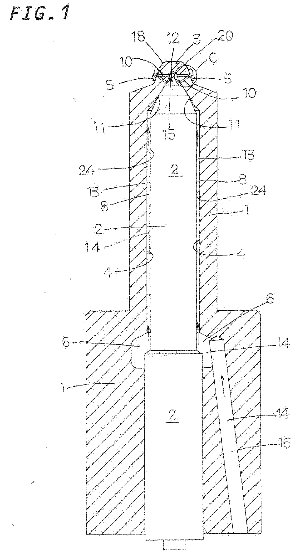
[0037]Embodiments of the liquid injection nozzle will now be described with reference to the drawings. First, the structure of the liquid injection nozzle will be roughly described with reference to FIGS. 1 and 2. This liquid injection nozzle can be applied, for example, to a fuel injection nozzle mounted on a diesel engine or a gasoline engine, or an exhaust gas purification apparatus which sprays liquid such as ammonia water or urea water. The liquid injection nozzle includes, as main components, a pipe-shaped nozzle body 1 which is fixed to a mounting portion of an engine, an injection apparatus, a combustion apparatus, or the like and having liquid passages 8 and 16 for supplying liquid; and a valve needle 2 which serves as a valve element and which is slidably inserted into a longitudinally extending hollow chamber 4 of the nozzle body 1 and forming a liquid reserving chamber 6. The injection hole structure of the liquid injection nozzle is generally characterized by the struct...

third embodiment

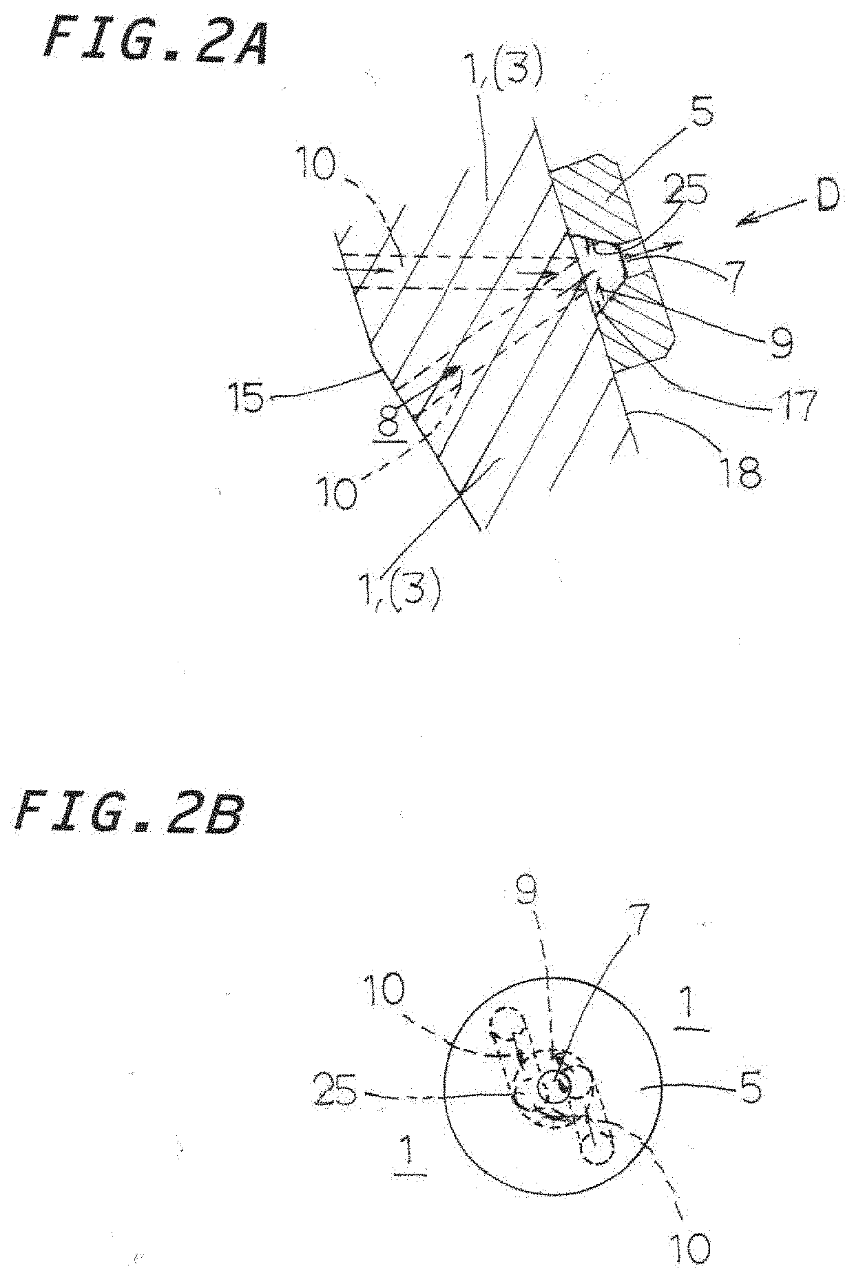
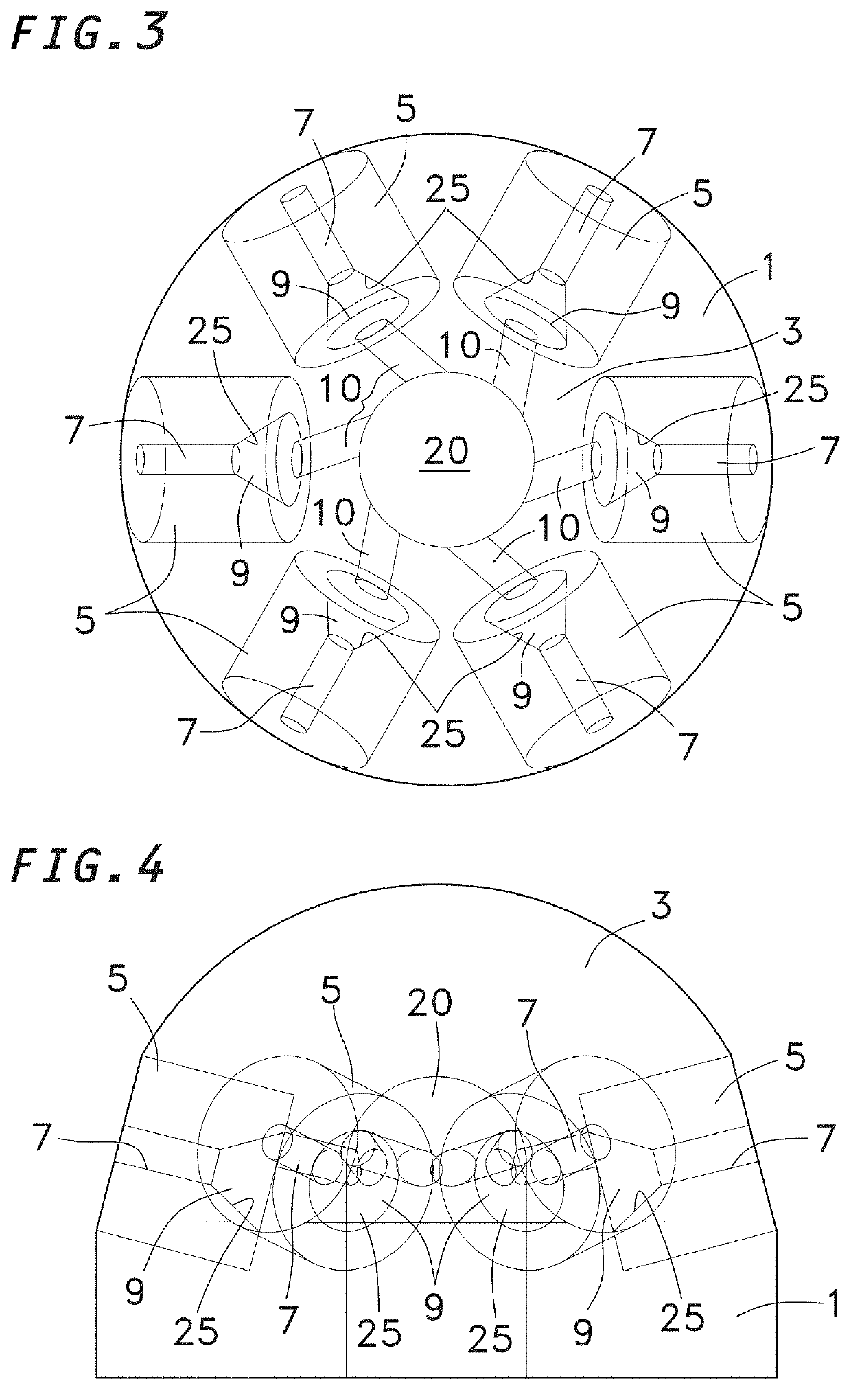
[0044]Next, the multi-injection-hole structure of the liquid injection nozzle will be described with reference to FIG. 7. FIG. 7 shows a see-through perspective view of the multi-injection-hole structure of the liquid injection nozzle of the present invention as viewed from the distal end side. FIG. 7 shows a see-through perspective view of the multi-injection-hole structure in which two distal end tips 5 are attached to the distal end portion 3 of the nozzle body 1. FIG. 7 shows the case where a single communication thin hole is formed in the distal end portion 3. In FIG. 7, the injection hole 7 and the swirling flow chamber 9 formed in each distal end tip 5 are shown three-dimensionally.

[0045]As described above, each of FIGS. 3 to 7 generally shows a see-through view of the distal end portion 3 of the nozzle body 1 for description of the distal end tips 5 and the communication thin holes 10, which are hollow spaces. Specifically, in these drawings, the outer shapes of the communic...


PUM


Abstract

This liquid injection nozzle atomizes and sprays liquid, while reducing loss of kinetic energy, thereby promoting mixing between the liquid and a gas and thus promoting the reaction between the liquid and the gas. In the liquid injection nozzle, a plurality of distal end tips each having an injection hole are provided on a distal end portion of a nozzle body. Each distal end tip has a conical swirling flow chamber. A communication thin hole is formed in the distal end portion. The communication thin hole extends from a hollow chamber to the conical swirling flow chamber of the distal end tip. When the valve needle is lifted, liquid flows through the communication thin hole into the swirling flow chamber in a tangential direction and generates a vortex flow, and the vortex flow is sprayed from the injection hole.

Description

FIELD OF THE INVENTION[0001]The present invention relates to a liquid injection nozzle for injecting liquid such as fuel, which is used in various types of apparatuses, for example, an engine, a combustor, and an exhaust gas purification apparatus.BACKGROUND OF THE INVENTION[0002]Conventionally, a liquid injection apparatus that injects liquid such as fuel or ammonia water is used in, for example, an engine, a combustor, and an exhaust gas purification apparatus. In the liquid injection apparatus, reserved high-pressure liquid is fed to a nozzle portion, and a valve needle in the nozzle portion is released from a valve seat so as to inject the high-pressure liquid into a chamber such as a liquid spraying chamber or a combustion chamber, whereby the liquid is sprayed. For example, since a common rail fuel injection apparatus can perform multi-stage injection of fuel at 2,000 bar or higher, the common rail fuel injection apparatus is employed in the latest engines. The biggest drawbac...

Claims


Application Information

Patent Timeline
IPC IPC(8): F02B23/10F02M61/18F02M45/02
CPCF02B23/10F02M2200/46F02M45/02F02M61/182F02M61/18F02M61/10F02M61/162F02M61/1806
Inventor MATSUOKA, HIROSHINOGUCHI, HIROSHIKISHISHITA, KEIJI
Owner ACR
Why Eureka
Try Eureka