Drive device for hybrid vehicle

Pending Publication Date: 2021-09-09
TOYOTA JIDOSHA KK
View PDF3 Cites 0 Cited by
  • Summary
  • Abstract
  • Description
  • Claims
  • Application Information

AI Technical Summary

Benefits of technology

The patent aims to address the issue of shocks occurring in hybrid vehicles when shifting gears. The invention suppresses these shocks while still allowing for quick activation of the engine. This is achieved by engaging a first engagement element while the electric motor is rotating at a low speed, which reduces the input speed to the transmission and prevents a sudden increase in pressure that could cause a shock.

Problems solved by technology

When the automatic transmission has its input shaft rotated and the engagement element included in the automatic transmission has an engagement state switched, there is a possibility that an inertia torque is generated and a shift shock occurs.
While the shift shock may be relaxed by gradually changing a hydraulic pressure supplied to the engagement element included in the automatic transmission, and thus switching the engagement state of the engagement element, doing so would impair responsiveness of gear shifting.
When the electrically driven hydraulic pressure source is alone actuated, it may not be able to appropriately supply hydraulic pressure for switching an engagement state of the engagement elements included in the automatic transmission.
Therefore, even if the first control is executed, it cannot suppress a shift shock appropriately.
Therefore, even if the second control is executed, it cannot suppress a shift shock appropriately.
When the hybrid vehicle is traveling at a vehicular speed equal to or faster than a threshold value, and the electric motor has a rotational speed decreased to a prescribed rotational speed, a shock may be caused as the rotational speed is changed.

Method used


Image

  • Drive device for hybrid vehicle
  • Drive device for hybrid vehicle
  • Drive device for hybrid vehicle

Examples


Embodiment Construction

[0033]Hereinafter, embodiments of the present disclosure will be described in detail with reference to the drawings. In the drawings, identical or equivalent components are identically denoted and will not be described redundantly.

[0034]

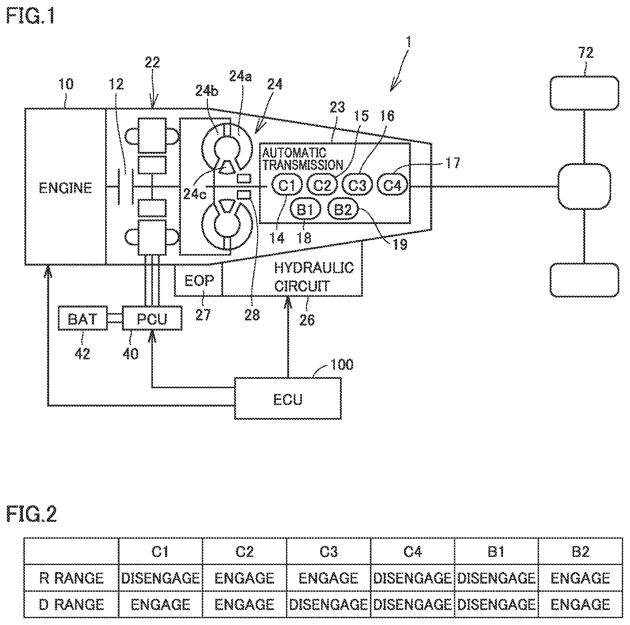
[0035]FIG. 1 generally shows a configuration of a hybrid vehicle 1 according to an embodiment. Hybrid vehicle 1 includes an engine 10, a K0 clutch 12, a motor generator 22, an automatic transmission 23, a torque converter 24, a hydraulic circuit 26, an electric oil pump (hereinafter also referred to as an “EOP”) 27, a mechanical oil pump (hereinafter also referred to as an “MOP”) 28, a power control unit (PCU) 40, a battery 42, a driving wheel 72, and an electronic control unit (ECU) 100. Hybrid vehicle 1 according to the present embodiment has at least an HV mode and an EV mode as travelling modes. The HV mode is a traveling mode using engine 10 and motor generator 22 as power sources. The EV mode is a traveling mode in which engine 10 is stopped an...


PUM


Abstract

An ECU executes a first control when an automatic transmission has a shift range changed from an N range to a D range. In the first control, the ECU initially rotates an EOP and also sets a motor generator's rotational speed to a prescribed rotational speed. The ECU rapidly engages a Drive clutch while maintaining the motor generator's rotational speed at the prescribed rotational speed. The ECU then increases the motor generator's rotational speed to a target rotational speed set for the D range.

Description

[0001]This nonprovisional application is based on Japanese Patent Application No. 2020-038151 filed on Mar. 5, 2020 with the Japan Patent Office, the entire contents of which are hereby incorporated by reference.BACKGROUNDField[0002]The present disclosure relates to a drive device for a hybrid vehicle.Description of the Background Art[0003]Japanese Patent Laid-Open No. 2015-217914 discloses a hybrid vehicle comprising an engine, a motor generator, a K0 clutch provided between the engine and the motor generator, and an automatic transmission that transmits power of at least one of the engine and the motor generator to a driving wheel. In the hybrid vehicle, when the automatic transmission has a shift range changed, an engagement element included in the automatic transmission has an engagement state switched to form a shift range applied after the previous shift range is changed.SUMMARY[0004]In the hybrid vehicle disclosed in Japanese Patent Laid-Open No. 2015-217914, no consideration...

Claims


Application Information

Patent Timeline
IPC IPC(8): B60W20/30F16H61/04B60W10/08B60W10/115
CPCB60W20/30B60W10/115B60W10/08F16H61/0437B60K6/547B60K6/365B60K6/24B60K6/26F16H2061/0488B60Y2200/92F16H63/50Y02T10/72B60K6/387B60K2006/4825B60W10/06B60W10/11B60W2510/0208B60W2710/021B60W2510/081B60W2710/081B60W2520/10B60W10/023B60L1/003B60W10/30B60W20/40B60W2030/203B60W2050/0042B60W30/19B60L15/007B60K6/48Y02T10/62Y02T10/64
Inventor HASEGAWA, YOSHIOAKIRA, TAKESHI
Owner TOYOTA JIDOSHA KK
Why Eureka
Try Eureka