[0009]As described above, in the present invention, a structure is employed that connects the front-rear tethers to the cross tether; therefore, tension is applied to the front-rear tethers by inflation gas when the airbag deploys, while the front protection part is attracted toward the vehicle front (inflator side) at the connections with the front-rear tethers. This causes the connections with the front-rear tethers to be recessed when viewed from the occupant side, with a protrusion formed between the recessed portions. This protrusion can soften the surface of the front protection part and gently receive the head of the occupant, consequently mitigating the
impact on the head of the occupant and preventing the turning of the head of the occupant. Thereafter, when the inflation gas spreads throughout the entire airbag, the tension in the front-rear direction of the front-rear tethers decreases, while the tension of the front protection part increases. At this time, since the front-rear tethers are connected to the cross tether, the front-rear tethers are drawn frontward by the cross tether and a
time difference occurs until the protrusion formed between the front-rear tethers fully extends in the width direction, extending the time to maintain the shape of the protrusion, although in a short period of time. In other words, compared to the case in which the front ends of the front-rear tethers are connected directly to the inner surface of the airbag, a slight time
delay occurs until the tension of the front protection part reaches the maximum after the tension of the front-rear tethers has decreased, extending the time for the front protection part to maintain a flexible state.
[0010]Connections between the rear end of the first front-rear tethers and the front protection part may be structured so as to be located at the boundaries between the front protection part and the side protruding parts. This also causes the airbag (the front protection part) to be pulled frontward by the first front-rear tethers, allowing the side protruding parts to clearly protrude relative to the front protection part.
[0011]The portion between connections of the cross tether with the pair of first front-rear tethers may be configured so as to move further in the occupant direction by a predetermined distance than a straight line connecting the portions at which the both ends of the cross tether are connected to the inner surface of the airbag when the airbag deploys. The cross tether that has moved in the occupant direction during the deployment of the airbag subsequently exhibits a behavior of returning frontward as a reaction. Consequently, while the airbag is deploying in the left-right width direction, a long distance can be ensured for the front-rear tethers to be drawn frontward by the cross tether, enabling further lengthening of the time in which the shape of the protrusion formed between the front-rear tethers is maintained.
[0017]As described above, by providing a pair of second front-rear tethers in addition to the pair of first front-rear tethers, a plurality (three) of protrusions having a small curvature
radius are formed in the front protection part, allowing the flexibility (
cushioning) of the front protection part to be further improved.
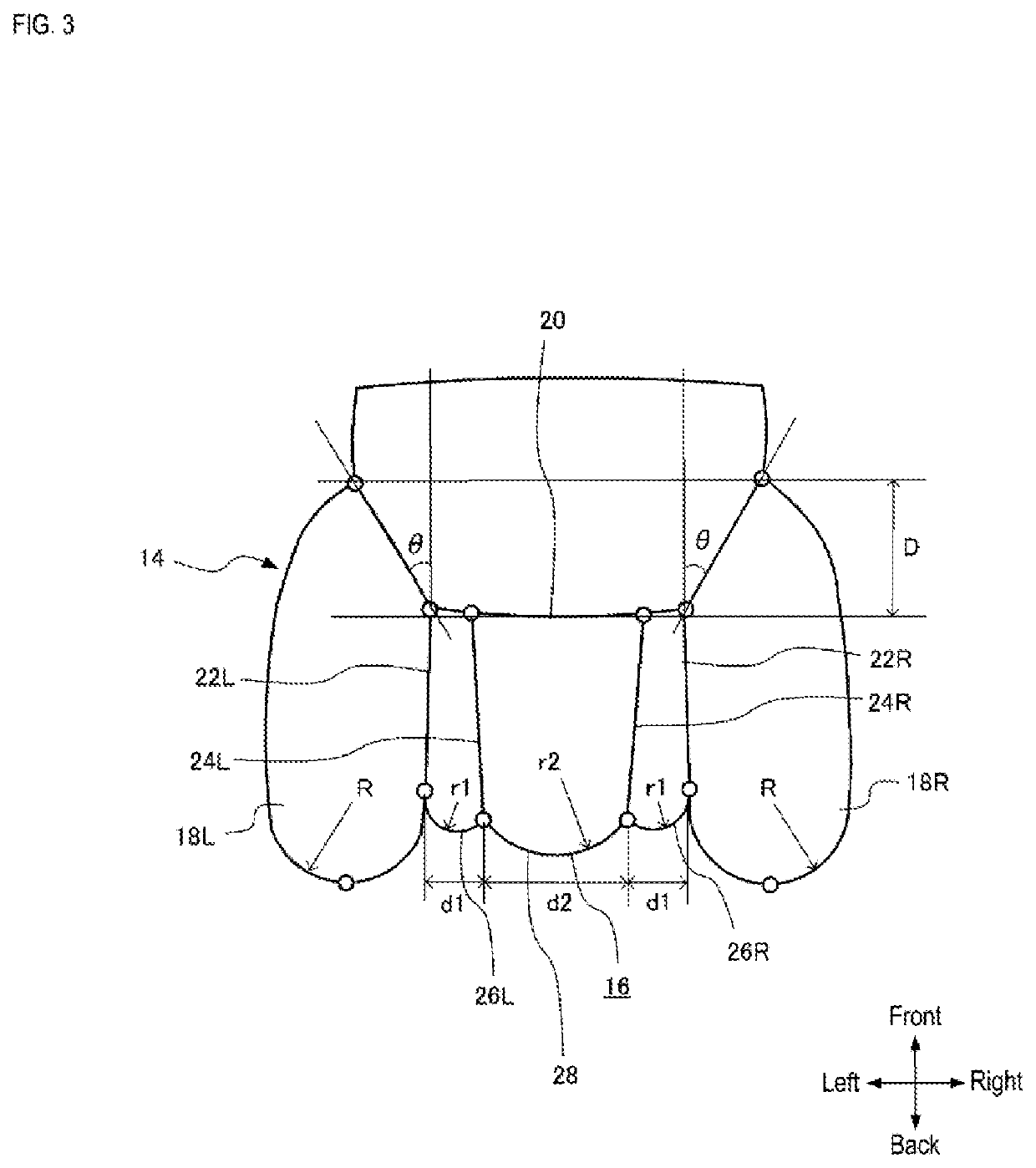
[0020]By making the curvature
radius (r1) of the intermediate protruding parts small, the flexibility (
cushioning) of the boundary portions between the front protection part and the side protruding parts increases, allowing the head of the occupant to be gently received when the head moves (slides) toward the side protruding parts in an oblique direction from the front protection part.
[0021]On the front protection part, the distance between the first front-rear tethers and the second front-rear tethers may be smaller than the distance between the pair of second front-rear tethers. Furthermore, the first front-rear tethers may be shorter than the second front-rear tethers. With such settings, it is possible to achieve the optimal curvature radii as described above by a relatively simple method.

