Manufacturing method and manufacturing device of element

a manufacturing method and element technology, applied in the direction of manufacturing tools, shaping tools, other domestic articles, etc., can solve the problems of material waste and product yield degradation, and achieve the effect of improving product yield and accurately molding the thin wall portion

Pending Publication Date: 2022-05-05
AISIN CORP +1
View PDF4 Cites 2 Cited by
  • Summary
  • Abstract
  • Description
  • Claims
  • Application Information

AI Technical Summary

Benefits of technology

[0006]It is an aspect of the element manufacturing method and the element manufacturing device of the present disclosure is to improve product yield while accurately molding the thin wall portion when an element having a thick wall portion and a thin portion is molded from a strip plate shaped material having a uniform thickness by performing punching work.Means for Solving the Problem
[0009]The element manufacturing method of the present disclosure manufactures an element that constitutes a transmission belt of a continuously variable transmission and that has a thick wall portion and a thin wall portion, by sequentially feeding a material having a strip shape with a uniform thickness to each press position and performing press working on the material at the press position. As the press working performed at the press position, the element manufacturing method includes: a preliminary punching step in which a cutting off portion other than a connecting portion is cut off from a surrounding material while the connecting portion connected to a surrounding material is left, and the cutting off portion is punched so as not to overlap with the surrounding material in a plate thickness direction; a crushing step of compressing and crushing a region of the cutting off portion which corresponds to the thin wall portion, after the preliminary punching step; and a punching step of punching the cutting off portion into an outer shape corresponding to the element, after the crushing step. In this way, since the cutting off portion is punched out so as not to overlap with the surrounding material in the plate thickness direction, and then the cutting off portion is compressed and crushed, the compressed material can smoothly flow in a plane direction. As a result, when the element is molded, the thin wall portion can be formed with high accuracy. In addition, this makes it possible to eliminate the need to form slits around the material in advance in order to secure the flow destination of the material in the crushing process, and to make the required slits smaller. Thus, the element can be taken out more efficiently from the material and the product yield can be improved. As a result, when the element having the thick wall portion and the thin wall portion is molded from the strip plate shaped material having a uniform thickness by performing punching work, the product yield can be improved while accurately molding the thin wall portion. When a pilot hole forming step in which a pilot hole for positioning the material in the subsequent step is formed in the material is provided before the preliminary punching step, since the cutting off portion and the surrounding material are displaced in the plate thickness direction, it is possible to suppress the material compressed by the crushing process from flowing toward the pilot hole to cause an adverse effect on the pilot hole.
[0011]The element manufacturing device of the present disclosure is provided with the dies (the preliminary punching die, the crushing die, and the punching die) for performing press working to realize each step of the above-described element manufacturing method of the present disclosure. Thus, an effect similar to the effect delivered by the element manufacturing method of the present disclosure can be delivered by the element manufacturing device. That is, when an element having a thick wall portion and a thin wall portion is molded from a strip plate shaped material having a uniform thickness by performing punching work, an effect of improving product yield while accurately molding the thin wall portion can be delivered.

Problems solved by technology

Thus, there is a problem that the material is wasted by just an amount of the size of the slit and the product yield is deteriorated.

Method used


Image

  • Manufacturing method and manufacturing device of element
  • Manufacturing method and manufacturing device of element
  • Manufacturing method and manufacturing device of element

Examples


Embodiment Construction

[0039]Next, modes for carrying out the present disclosure will be described with reference to the drawings.

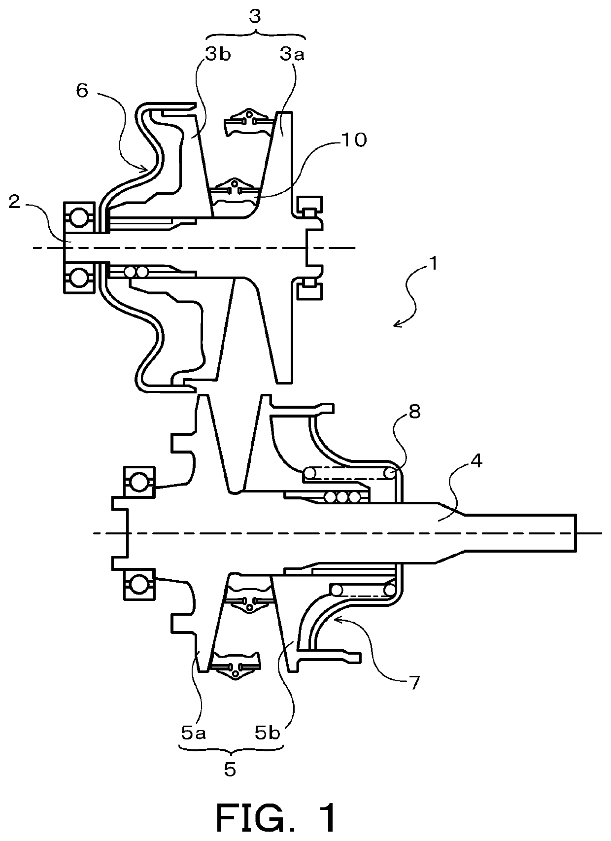
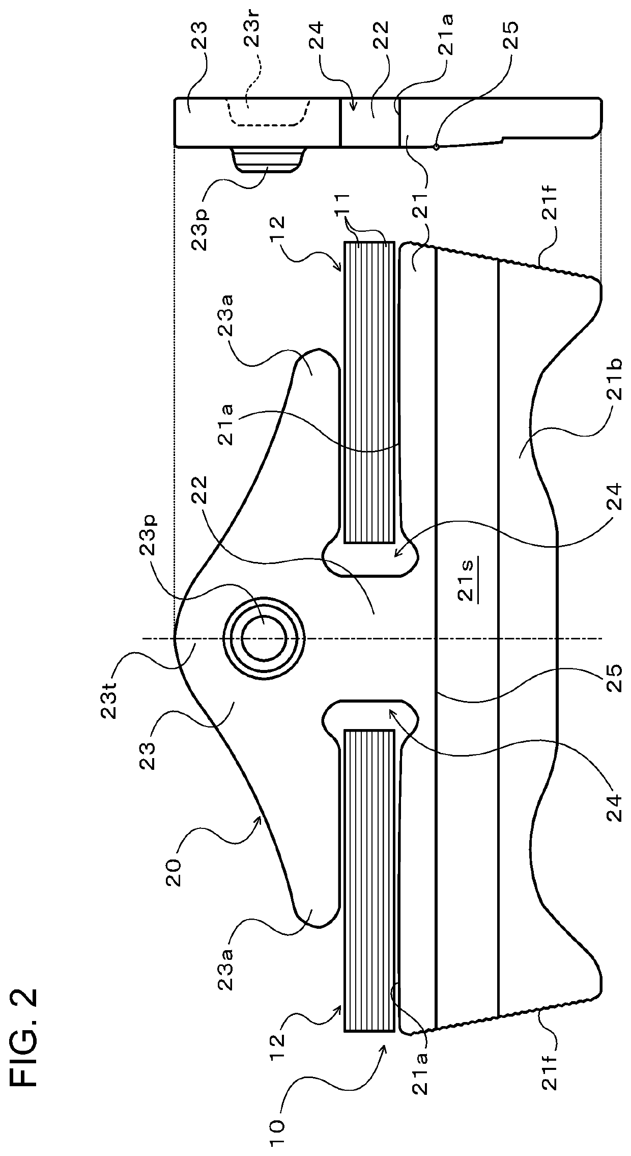
[0040]FIG. 1 is a schematic configuration view of a continuously variable transmission having a transmission belt, and FIG. 2 is a schematic configuration view of the transmission belt. As shown in FIG. 1, a continuously variable transmission 1 has a primary shaft 2 serving as a drive side rotation shaft, a primary pulley 3 provided on the primary shaft 2, a secondary shaft 4 serving as a driven side rotation shaft disposed in parallel with the primary shaft 2, and a secondary pulley 5 provided on the secondary shaft 4. A transmission belt 10 is wound around a pulley groove (V-shaped groove) of the primary pulley 3 and a pulley groove (V-shaped groove) of the secondary pulley 5.

[0041]The primary shaft 2 is coupled to an input shaft, which is not shown, coupled to a power generation source such as an engine (internal combustion engine) via a forward / backward switching mechanism,...


PUM

PropertyMeasurementUnit
thicknessaaaaaaaaaa
widthaaaaaaaaaa
shapeaaaaaaaaaa

Abstract

An element manufacturing method for a transmission belt of a continuously variable transmission having a thick wall portion and a thin wall portion formed by sequentially feeding a material having a strip shape with a uniform thickness to each press position and performing press working on the material at the press position. The method includes, as the press working performed at the press position: a preliminary punching step in which a portion other than a connecting portion is cut off from surrounding material and the cut off portion is punched so as not to overlap with the surrounding material in a plate thickness direction; a crushing step of compressing and crushing a region of the thin walled cut off portion, after the preliminary punching step; and a punching step of punching the cutting off portion into an outer shape corresponding to the element, after the crushing step.

Description

CROSS REFERENCE TO RELATED APPLICATIONS[0001]This application is a National Stage of International Application No. PCT / JP2020 / 013553 filed Mar. 26, 2019, claiming priority based on Japanese Patent Application No. 2019-067572 filed Mar. 29, 2019, the contents of which are incorporated by reference in their entirety.TECHNICAL FIELD[0002]The present description discloses a manufacturing method and a manufacturing device of an element.BACKGROUND ART[0003]Conventionally, as this type of element manufacturing method, a manufacturing method in which an element configured of: a body portion having left and right side surfaces that are in contact with a pulley of a continuously variable transmission and having a tapered portion that tapers downward (or a parallel thin wall portion extending downward); a neck portion extending upward from the body portion; and a triangular head portion extending upward from the neck portion, is manufactured from a strip-shaped material having a uniform thickn...

Claims


Application Information

Patent Timeline
Patent Type & Authority Applications(United States)
IPC IPC(8): B21D28/26
CPCB21D28/26F16G5/16B21D53/14B21D28/10B21D37/08B21D35/001
Inventor TAKEUCHI, YASUHIROASAMI, TORUMIYATA, KAZUHISAHATA, HIROTAKAOKANO, MASAYUKI
Owner AISIN CORP
Why Eureka
Try Eureka