
Method for modal analysis of bridge structures based on surveillance videos

Active Publication Date: 2022-05-26
ZHEJIANG UNIV
View PDF4 Cites 0 Cited by
  • Summary
  • Abstract
  • Description
  • Claims
  • Application Information

AI Technical Summary

Benefits of technology

The technology described in this patent has advantages over existing surveillance cameras. It uses existing cameras and doesn't need to install new monitoring equipment, reducing sensors and the number of acceleration sensors needed. The instruments and equipment are simple and can be easily installed without affecting the structure or traffic conditions. The problem of distortion when calculating spatial coordinates or displacements is solved, resulting in improved monitoring precision and accuracy.

Problems solved by technology

Due to the influences of imperfect design theories, material limitation during construction, defects of construction quality, sudden overload disasters and the like, some bridges have great potential safety hazards in operation.
Due to fatigue and aging of materials of the bridges, collapse accidents of the bridges constantly emerge, resulting in a large number of economic losses and casualties.
A method using the contact sensor for surveillance is higher in accuracy, but difficult in installation and maintenance; and meanwhile, the original structure is damaged, and the method has great limitation.
The method is usually used for detecting the structure of the bridge; and as the detection frequency is lower, the method is difficult to apply to long-term surveillance for the structure.
Additionally, the road is blocked when in detection, which affects vehicle traffic; and the detection is difficult to implement in heavy traffic sections.
Through adoption of the previous computer vision method, in order to realize surveillance for the structure of the whole bridge, a camera is usually arranged at the position which is far away from the bridge, and it is difficult to ensure the measurement accuracy.
Two problems in calling for the surveillance camera on the bridge are that: the surveillance camera is difficult to cover the bridge; and meanwhile, a picture of a nearby place, which is shot by the surveillance camera, has great distortion, and the identification for the displacement of the bridge is affected.

Method used


Image

  • Method for modal analysis of bridge structures based on surveillance videos

Examples


Embodiment Construction

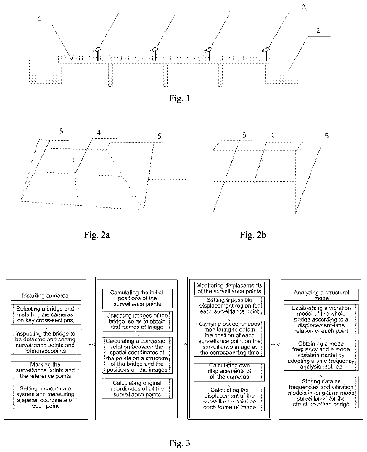
[0045]The specific implementation manner of the present invention is further described hereinafter in combination with a schematic diagram of arrangement of instruments shown in FIG. 1, a schematic diagram of restoring of distortion shown in FIG. 2 and a flow chart of implementation shown in FIG. 3. The method includes the following steps:

[0046]A. installing cameras and calibrating surveillance points and reference points;

[0047]A1. installing a plurality of cameras 3 on a bridge 1 to be detected and ensuring the adjacent cameras to be in surveillance regions thereof;

[0048]A2. inspecting the bridge to be detected; comprehensively considering the surface of a road, handrails, the positions of the surveillance cameras and surveillance regions; selecting the surveillance points 4 and the reference points 5 as required; ensuring no shielding of barriers between all the points and the surveillance cameras when the points are selected; and selecting at least four reference points;

[0049]A3....


PUM


Abstract

A method for modal analysis of bridge structures based on surveillance videos is provided. A plurality of continuous cameras are utilized for realizing high-precision surveillance for the structure of the bridge. Firstly, a plurality of regions are selected in the viewing angle of each of the cameras, and a conversion relation between images of the regions and actual displacements is calculated; next, displacements on the images shot by the cameras are converted into actual displacements of targets, so as to obtain displacements of the targets relative to the cameras; displacements of the adjacent cameras are sequentially passed according to a difference value from the ground of an abutment, so as to obtain displacements of all camera bodies; and finally, the displacements of all the targets relative to the ground of the abutment are calculated, and the structural mode of the bridge is calculated.

Description

CROSS-REFERENCE TO RELATED APPLICATIONS[0001]This application claims the benefit of priority from Chinese Patent Application No. 202011337886.0, filed on Nov. 25, 2020. The content of the aforementioned application, including any intervening amendments thereto, is incorporated herein by reference in its entirety.TECHNICAL FIELD[0002]The present invention relates to a method for modal analysis of bridge structures.BACKGROUND OF THE PRESENT INVENTION[0003]The structure of a bridge, in particular to a long span bridge, experiences long-term deflection changes due to the influences of continuous and short-term loads, including stress redistribution caused by dead weight, pre-stress, traffic, temperature change and damage. Due to the influences of imperfect design theories, material limitation during construction, defects of construction quality, sudden overload disasters and the like, some bridges have great potential safety hazards in operation. Due to fatigue and aging of materials of...

Claims


Application Information

Patent Timeline
IPC IPC(8): H04N7/18
CPCH04N7/181G06T7/0004G06T7/20G06T2207/10016G06T2207/30232G06T5/80
Inventor YE, XIAOWEILI, ZHEXUNJIN, TAO
Owner ZHEJIANG UNIV
Learn More