Intubation Shield

a technology of intubation shield and shield body, which is applied in the field of medical devices, can solve the problems of limiting both movement, difficult to move, physical awkwardness, and difficulty in using present intubation boxes, and achieves the effects of improving the visibility of the practitioner, easy movement, and reducing the difficulty of movemen

Pending Publication Date: 2022-06-09
INLINE PLASTICS
View PDF0 Cites 1 Cited by
  • Summary
  • Abstract
  • Description
  • Claims
  • Application Information

AI Technical Summary

Benefits of technology

[0006]The present invention cures the deficiencies noted above by providing an intubation that is flexible, stackable, lightweight, and easy to move. Moreover, the presently disclosed intubation shields can include a viewing panel to improve the visibility of the practitioner and arm holes arranged and configured to increase the freedom of movement of the arms of the medical practitioner.
[0007]The present disclosure also provides intubation shields which can be made using thermoforming techniques from materials such as polyethylene terephthalate (PET). More specifically, disclosed are thermoformed intubation shields which are adapted and configured to be placed over the head and portions of the neck, torso or both of a patient quickly. The disclosed shields include a flat viewing panel to improve the visibility of the oropharyngeal airway and with arm holes that are positioned on the sides of the intubation shield to maximize the freedom of movement of the arms of the practitioner performing an intubation or other procedures on the head, neck or upper torso of the patient.
[0009]In accordance with certain embodiments, the intubation shield can include arm holes that are positioned on the first and the second side walls that allow the practitioner to maximize the freedom of movement of the practitioner performing an intubation or other procedures on the head, neck or upper torso of the patient. Preferably, the arm holes can be an oblong or slotted hole to allow for greater movement.
[0010]Preferably, the intubation shield can move with the practitioner to provide a barrier between the upper body of the patient and the practitioner. For example, the intubation shield is lightweight and can move when the practitioner moves his arms and can momentarily lift above the bed level while maintaining the barrier between the upper body of the patient and the practitioner. The gaps at the bed level may not be a concern when the shield shifts up in response to the movement of the arms of the practitioner. In accordance with some embodiments, the intubation shield can be thermoformed to reduce the weight.
[0011]In certain embodiments, the intubation shield can be disposable and recyclable. For example, the intubation shield can be a thermoformed PET (polyethylene terephthalate) intubation box, which can be disposed of and recycled. In accordance with some embodiments, due to its ease of use and lightweight construction, the thermoformed PET intubation shield can travel with the patient in contrast to traditional intubation boxes made using Plexiglas. In accordance with some embodiments the intubation shield can be reused for the same patient or disinfected and used for different patient.
[0012]In accordance with some embodiments, the intubation shield can be a soft cornered shield with the viewing panel to eliminate visibility issues caused by seams and horizontal walls. In accordance with some embodiments, the intubation shield can include a slight flare on the walls to allow for nesting of the intubation shields while the intubation shields are shipped and / or stored.

Problems solved by technology

However, certain of these prior intubation boxes are rigid, heavy and difficult to move, which limits both, the placement over the patient and the movement of the practitioner's arms.
Specifically, the limited arm movement makes the present intubation boxes difficult to use or physically awkward during emergencies where rapid intubation is required.
Moreover, these current intubation boxes are often made from Plexiglas and need to be sterilized and require a 20-30 minute rest time before they are ready for use.
Still further, the seams of these current intubation boxes limit visibility of the patient.
Yet another disadvantage of these current intubation boxes is that they are not stackable or nestable which increases the space required for shipment and storage and therefore, can limit the number of units that are available in close proximity to emergency rooms.
These intubation boxes inhibit the visibility of the patient if the plastic membrane folds over itself or crumbles / creases, are difficult to move, can be easily ruptured increasing the risk of droplet contamination and restrict the freedom of movement of the arms of the patient due to the thin plastic membrane being inflexible if the plastic membrane is pulled tight over the supporting structure to improve visibility.
Also, the supporting structures used in these boxes can be difficult to assemble and obscures patient visibility.

Method used


Image

  • Intubation Shield
  • Intubation Shield
  • Intubation Shield

Examples


Embodiment Construction

[0020]In the following description, it is understood that terms such as “top,”“bottom,”“outward,”“inward,”“internal,”“external,” and the like are words of convenience and are not to be construed as limiting terms. Reference will be made in detail to exemplary embodiments of the disclosure, which are illustrated in the accompanying figures and examples. Referring to the drawings in general, it will be understood that the illustrations are for the purpose of describing particular embodiments of the disclosure and are not intended to limit the same.

[0021]Referring now to the drawings, wherein like parts are marked throughout the specification and drawings with the same or similar reference numerals. Drawing figures are not necessarily to scale and in certain views, parts may have been exaggerated for purposes of clarity.

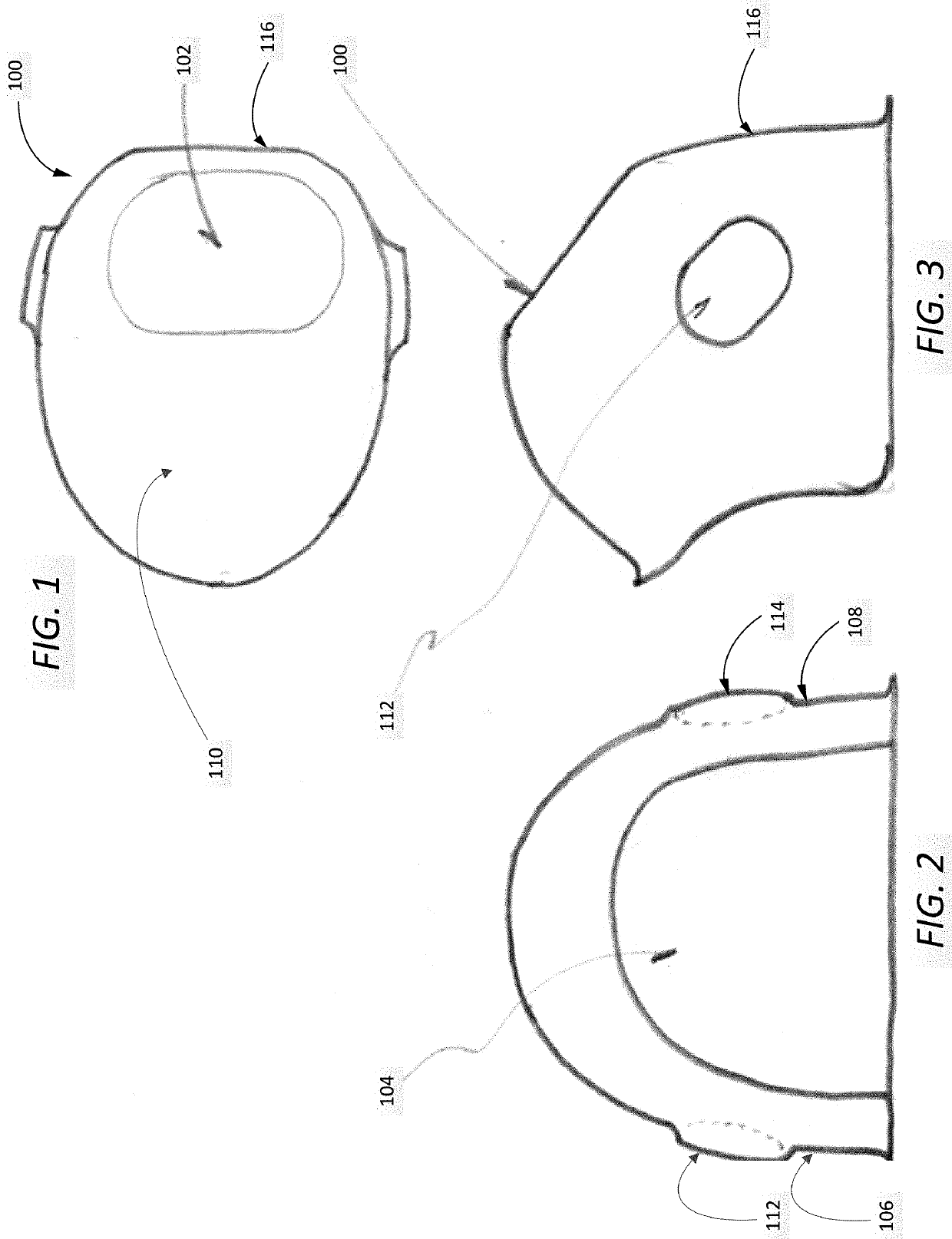
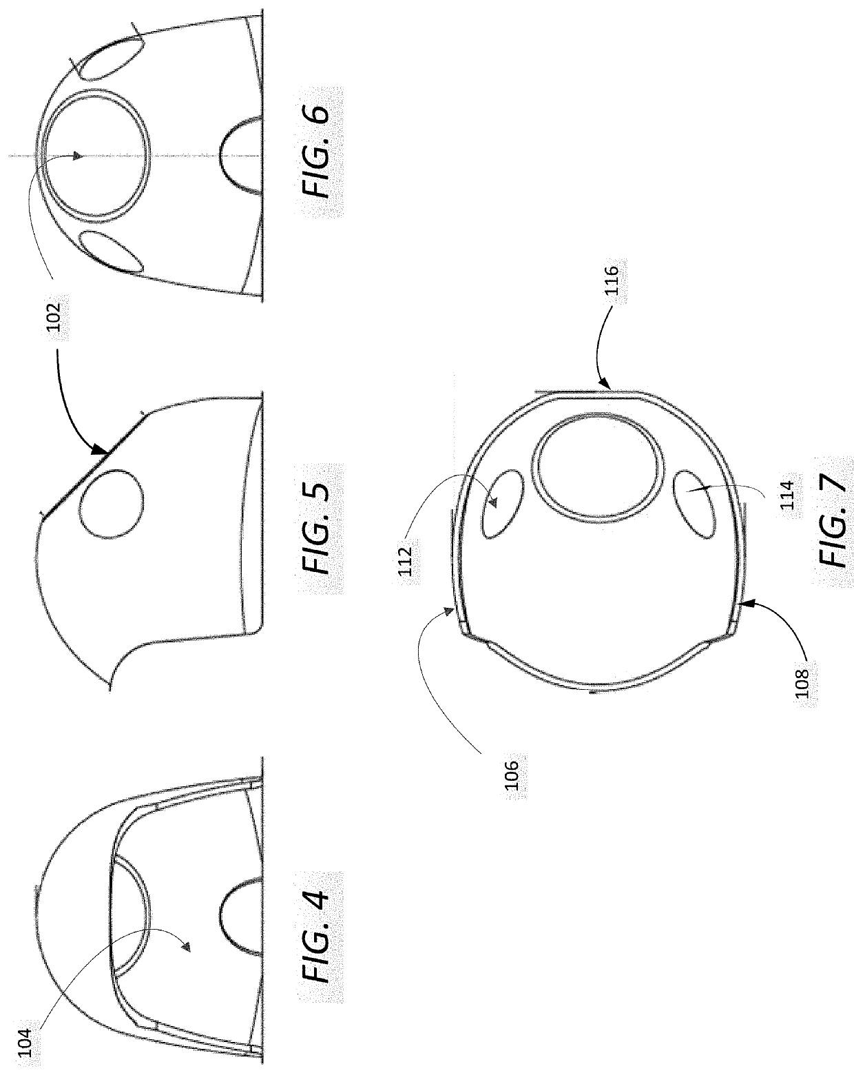
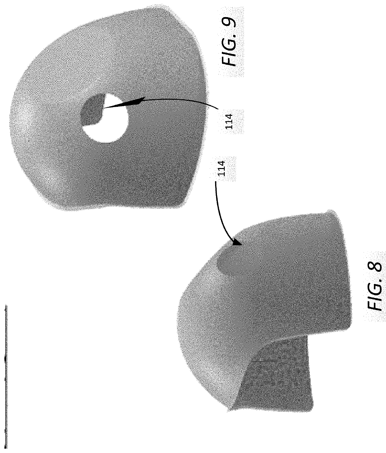
[0022]FIGS. 1, 2 and 3 depict an intubation shield 100 constructed in accordance with an embodiment of the present invention. In an embodiment, the intubation shield 10...


PUM


Abstract

An intubation shield having a viewing panel and a front opening surrounded by a first side wall, a second side wall, a back wall and a front dome wall configured to cover at least a portion of the head, the neck and / or the upper torso of a patient to form a barrier between the covered parts of the patient and the upper body of the practitioner, wherein the viewing panel allows for uninterrupted visibility of an anatomical feature of the patient, and the front opening allows the body of the patient to be inserted while minimizing the droplet contamination, and a first arm hole on the first side wall and a second arm hole on the second side wall to increase the freedom of movement of the practitioner while performing medical procedures.

Description

CROSS-REFERENCE TO RELATED APPLICATION[0001]The present application claims the benefit of priority to U.S. Provisional Patent Application Ser. No. 63 / 121,095 filed on Dec. 3, 2020, which is herein incorporated by reference in its entirety.FIELD OF THE DISCLOSURE[0002]The present disclosure generally relates to a medical apparatus and methods for using the same and, more particularly to, intubation shields and their use and, still further, to intubation shields which are made using thermoforming techniques from materials such as polyethylene terephthalate (PET).BACKGROUND OF THE DISCLOSURE[0003]Various intubation boxes have been developed for medical use. Use of such intubation boxes has increased during the coronavirus pandemic. However, certain of these prior intubation boxes are rigid, heavy and difficult to move, which limits both, the placement over the patient and the movement of the practitioner's arms. Specifically, the limited arm movement makes the present intubation boxes ...

Claims


Application Information

Patent Timeline
Patent Type & Authority Applications(United States)
IPC IPC(8): A61M16/04
CPCA61M16/0488A61M2205/02A61M2209/088A61B46/20A61M2205/583
Inventor IVENITSKY, VICTORKHARBANDA, RAGHAVMELLO, KEVINLASOTA, JERZYJIMENEZ, GREGORYMELLEN, SUSANNA
Owner INLINE PLASTICS
Why Eureka
Try Eureka