
Sensing Arrangement for Monitoring Contamination of Cover Slide on Laser Processing Head

Pending Publication Date: 2022-06-09
II VI DELAWARE INC
View PDF0 Cites 0 Cited by
  • Summary
  • Abstract
  • Description
  • Claims
  • Application Information

AI Technical Summary

Benefits of technology

The patent describes an apparatus and method for a laser processing head with a replaceable cover optic. The head includes a receptacle for holding the cover optic, a reflector, and an offset sensor for detecting radiation reflected by the reflector. The reflector is positioned near the receptacle and the sensor is positioned near the edge of the cover optic. The sensor detects the reflected radiation and the level of contamination on the cover optic is determined based on the detected radiation. The technical effect of this invention is to provide a more efficient and easy way to replace the cover optic in a laser processing head, while also improving the accuracy and speed of detecting contamination on the cover optic.

Problems solved by technology

If the pressure of the assist gas is too high, then excess spatter may stick to the nozzle and the cover slide of the laser processing head.
Some lasing operations and some materials may produce more contaminants than others.
For example, cutting galvanized materials can release microscopic particles from the material's zinc coating, producing a very fine dust.
Also, contamination inside the laser processing head can build up on the inside surface of the cover slide and can interfere with operation.
Also, scattered light from the cover slide can heat and damage other components of the processing head or can interfere with their operation.
Unfortunately, the signal that is detected depends a great deal on characteristics of the surface of at the edge of the cover slide, and sometimes also depends on the surface of the mount in which the cover slide is held.
Some areas of the cover slide may not contribute to the detected stray light signal at all, meaning the measurement of the cover slide's contamination may be inaccurate.
The needed space for the pyrometer can complicate the arrangement of lasing optics, can alter the distance the cover slide can have from the lasing process, and can interfere with other parameters of the laser processing head.

Method used


Image

  • Sensing Arrangement for Monitoring Contamination of Cover Slide on Laser Processing Head
  • Sensing Arrangement for Monitoring Contamination of Cover Slide on Laser Processing Head
  • Sensing Arrangement for Monitoring Contamination of Cover Slide on Laser Processing Head

Examples


Embodiment Construction

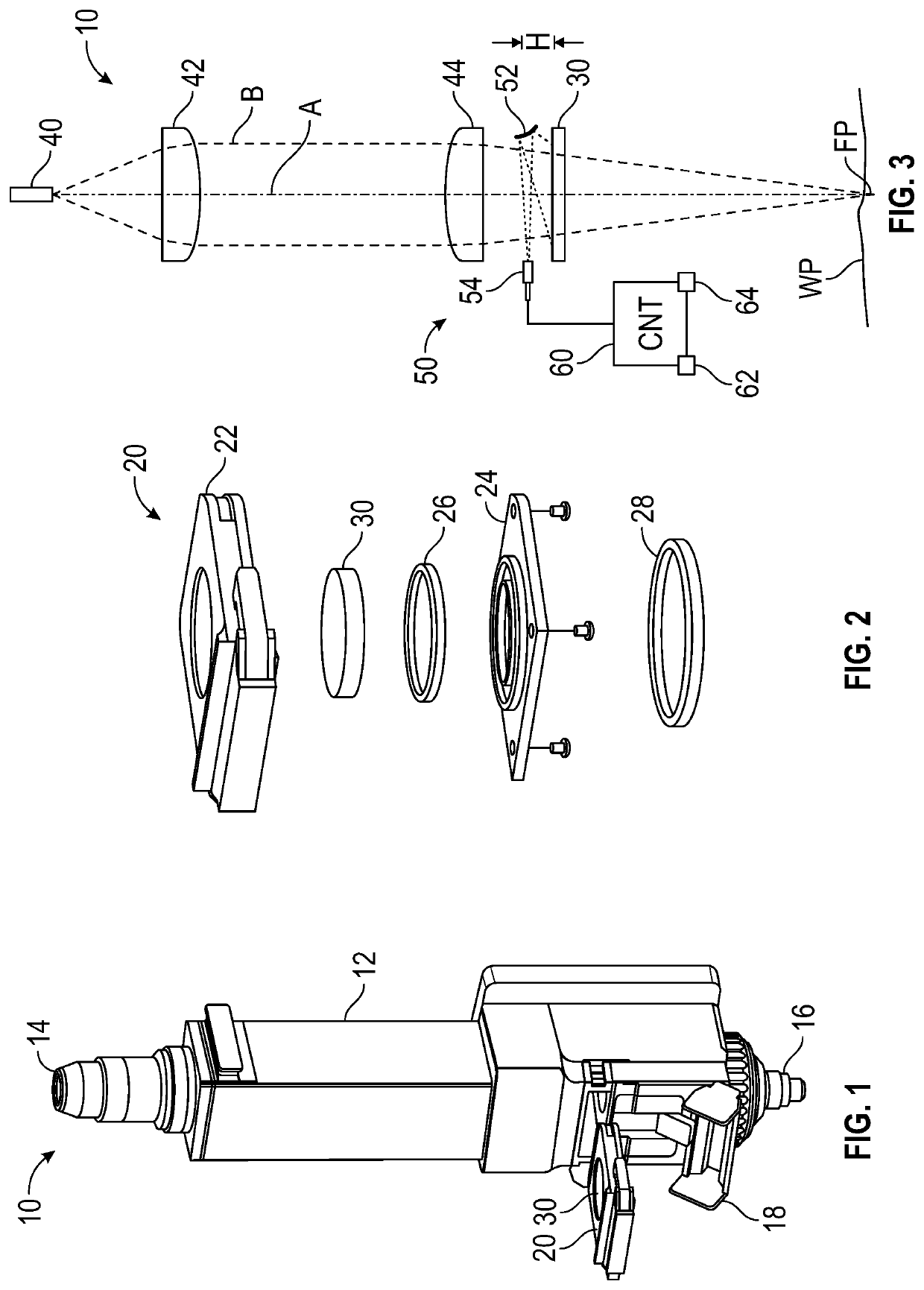
[0023]FIG. 1 illustrates a perspective view of an example of a laser processing head 10 according to the present disclosure. The laser processing head 10 includes a housing 12 for internal optics. A connection 14 at one end of the housing 12 can couple to a laser cable, which conducts the laser energy into the head 12. An output or nozzle 16 at the other end of the housing 12 allows the focused laser beam to be emitted from the housing 12 for achieving the purposes of the lasing operation, such as welding, additive manufacture, cutting, etc. This particular arrangement with the nozzle 16 is a cutting head 10. In general, the cutting head 10 may benefit from the features disclosure herein more than a welding or other type of head.

[0024]To protect the internal optics inside the housing 12, the head 10 includes a cover slide cartridge 20 that holds a replaceable cover optic, cover slide, or protective window 30. This cover optic 30 acts as a transparent window between the interior of t...


PUM

PropertyMeasurementUnit
Timeaaaaaaaaaa
Radiusaaaaaaaaaa
Wavelengthaaaaaaaaaa

Abstract

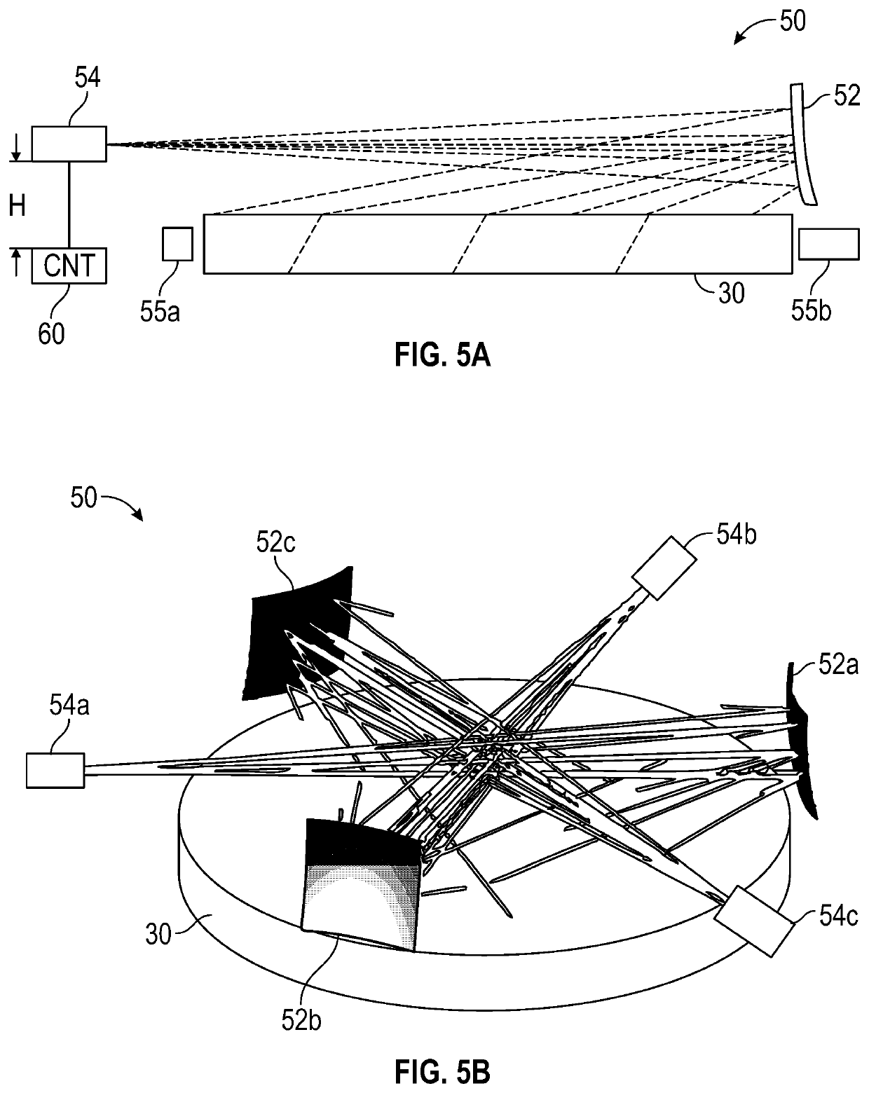
A sensing apparatus monitors a cover optic on a laser processing head for contamination, indicating the need to replace the cover optic. The apparatus includes at least one reflector and at least one sensors that are disposed in the processing head adjacent a periphery of the cover optic. The reflector reflects radiation from the laser beam deflected from contamination on the cover optic and incident thereagainst. The sensor is offset from the reflector and detects at least a portion of the radiation reflected by the reflector. A controller in communication with the sensor can determine the contamination on the cover optic based on the detected radiation.

Description

FIELD OF THE DISCLOSURE[0001]The subject matter of the present disclosure is directed to monitoring for contamination on an optical element, and in particular to monitoring for contamination on a cover slide of a laser processing head.BACKGROUND OF THE DISCLOSURE[0002]In materials processing, a cover slide is used in a laser processing head to protect internal lasing optics. For example, a laser cutting head produces a laser beam that melts a target material. An assist gas evacuates molten material to create a kerf in the workpiece. The pressure and volume of the assist gas is carefully controlled, especially when the laser is used to penetrate the material. If the pressure of the assist gas is too high, then excess spatter may stick to the nozzle and the cover slide of the laser processing head. Over time, the cover slide needs to be changed so contamination does not interfere with the laser beam.[0003]Some lasing operations and some materials may produce more contaminants than oth...

Claims


Application Information

Patent Timeline
IPC IPC(8): B23K26/70G01N21/94G05B19/406
CPCB23K26/707G01N21/94G05B19/406G05B2219/50203G01N2201/0636G05B2219/37275G01N2201/06113B23K26/702G01N2021/157G01N21/958
Inventor CHAN, DANNY
Owner II VI DELAWARE INC
Learn More