Vertical launch system

Inactive Publication Date: 2022-06-09
LOON LLC
View PDF0 Cites 2 Cited by
  • Summary
  • Abstract
  • Description
  • Claims
  • Application Information

AI Technical Summary

Benefits of technology

[0011]In another example, each wedge assembly comprises a wedge body and a base plate, with the wedge body being affixed to a respective one of the vertical supports and a respective one of the plurality of base members. In yet another example, the system further comprises a catwalk disposed along

Problems solved by technology

However, as lighter-than-air high altitude platforms (HAPs) are made larger to enhance their operational capabilities and lifespans, the inflated envelopes may become significantly larger than a portable launch rig can enclose, which can be adversely affected by the wind before launch

Method used


Image

  • Vertical launch system
  • Vertical launch system
  • Vertical launch system

Examples


example balloon

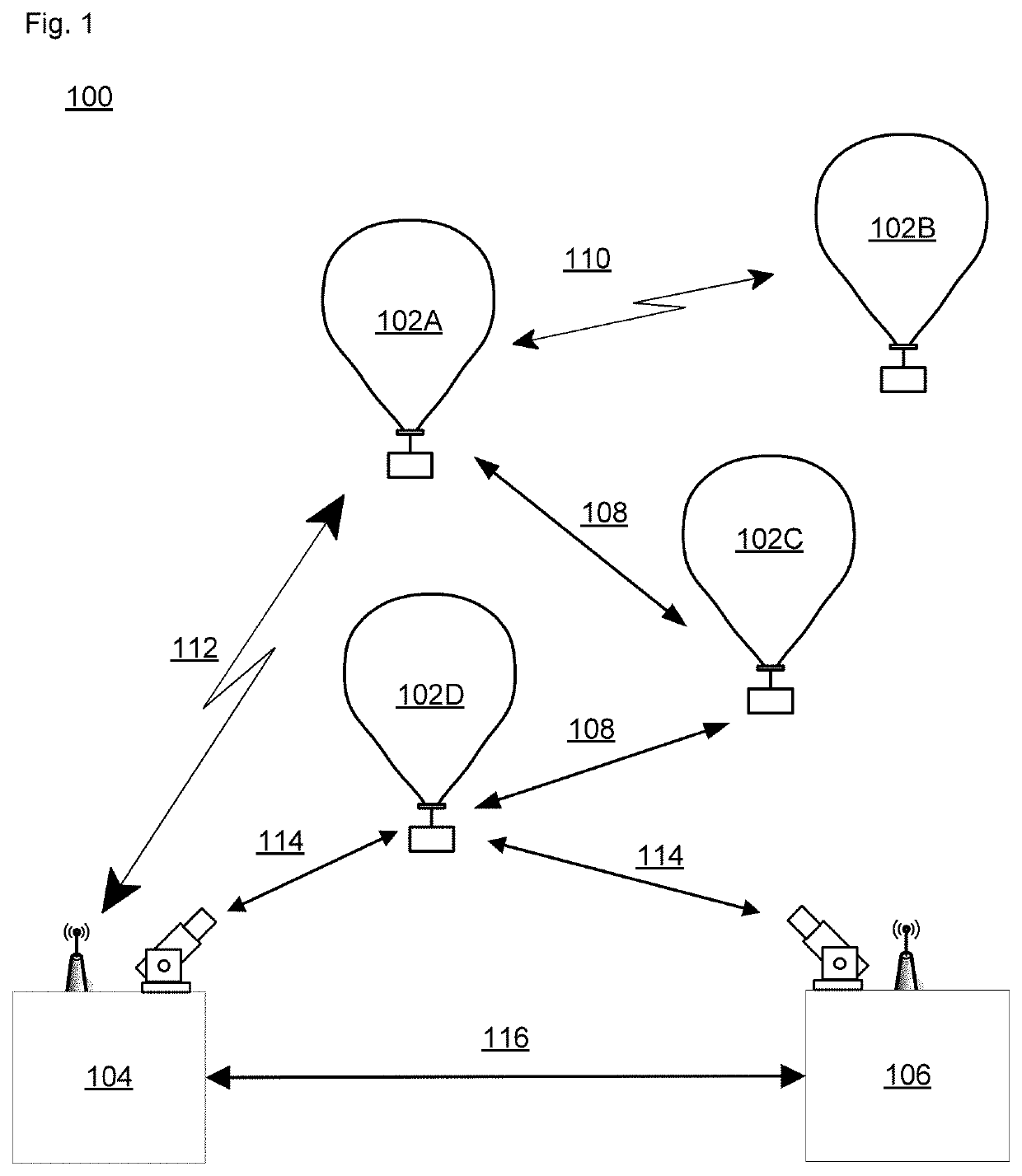
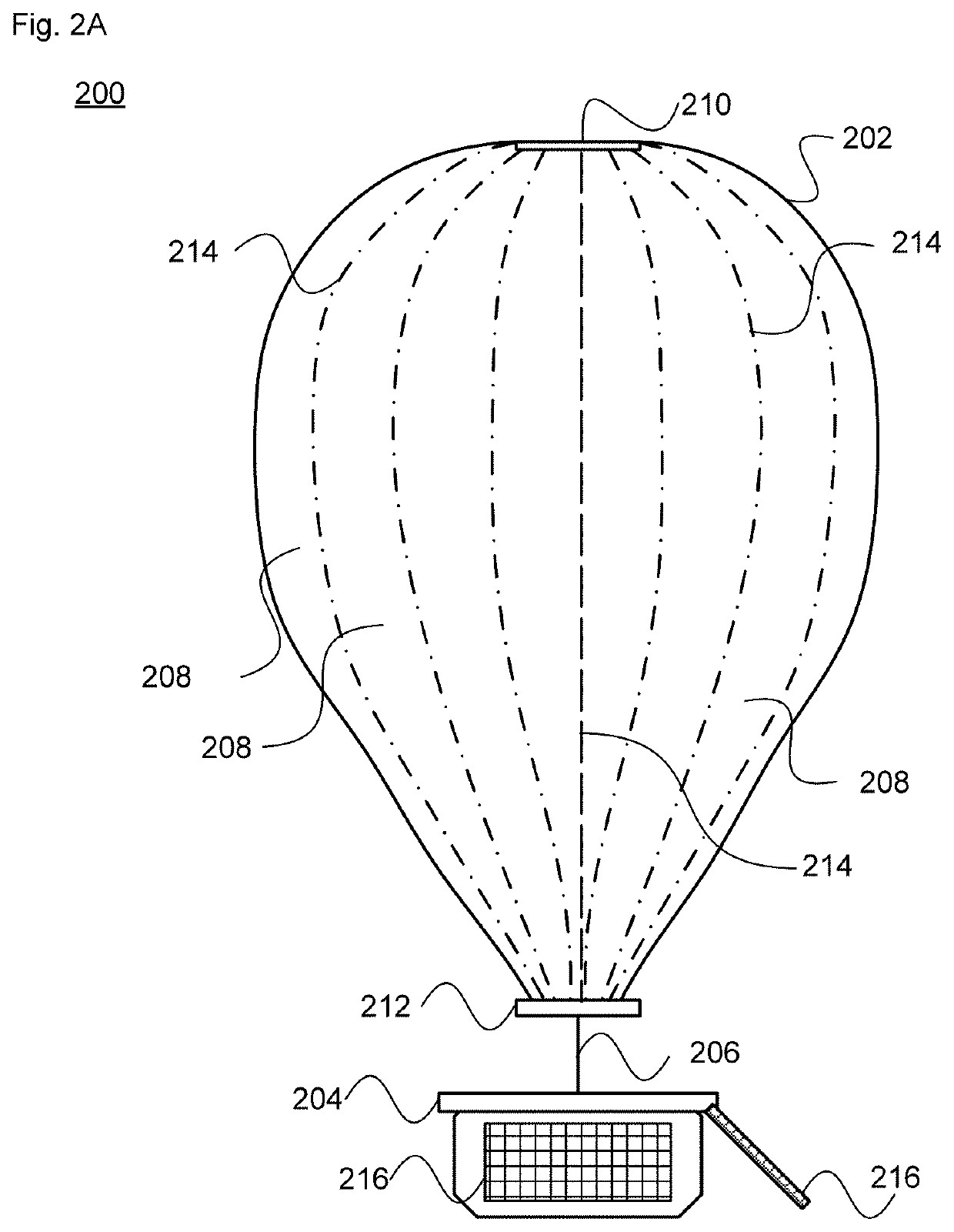
[0043]FIG. 2A is an example balloon 200, which may represent any of the balloons 102 of network 100. As shown, the balloon 200 includes an envelope 202 and a payload (e.g., a flight capsule) 204 connected to the envelope by a connection member 206 such as a down-connect or a tether. The balloon 200 may be configured, e.g., as a superpressure balloon and include one or more ballonets (not shown) to control buoyancy.

[0044]In a superpressure or other balloon arrangement, the envelope 202 may be formed from a plurality of gores 208 sealed to one another. An upper portion of the envelope 202 has an apex section configured for connection to an apex (or top) load ring or plate 210, and a lower portion having a base section configured for connection to a base load ring or plate 212 positioned at the bottom of the balloon envelope. Tendons (e.g., webbing or load tape) 214 are shown running longitudinally from the apex load ring 210 to the base load ring 212. The tendons are configured to pro...

example launch

Assembly

Launch Rig Support Structure

[0048]As shown in FIG. 3A, an example launch rig 300 includes a support structure 302 surrounding an interior space 304 configured for inflating and launching of HAPs such as balloon 306. In one example, the support structure 302 may be approximately 110-150 feet high and 80-120 feet wide. The support structure 300 may include a series of vertical supports 308 arranged in a circular or arcuate shape around a base 310. As shown, the vertical supports 308 are affixed to a set of base members (“torque tubes”) 312. The base members 312 rest on a track 314 of the base 310. A set of vertically aligned lateral support beams 316 couple each adjacent pair of vertical supports 308. As shown, a catwalk 318 may be disposed along a top region of the support structure 302 of the launch rig 300. FIGS. 3C-D illustrate views of the launch rig 300 with the balloon 306 omitted for clarity.

[0049]As shown in view 400 of FIG. 4A, the vertical supports may each be compr...

example payload release

Assembly

[0069]In order to lift, fill and launch the HAP, an arrangement may be provided that includes a configuration to support the HAP when it is in the launch platform. In accordance with aspects of the technology, a launch cart supports the HAP and a payload release assembly secures the HAP during lift and fill. The launch cart may be moved onto the central platform assembly via the payload bridge, for instance being loaded onto the payload bridge by a forklift.

[0070]FIG. 9A illustrates an example arrangement 900, in which a launch cart 902 supports a payload (e.g., a lighter-than-air balloon assembly) 904 on a carriage 906. The payload is transported along the payload bridge 806 until reaching the platform 808. The platform 808 is used as a work platform and supports the work operations of personnel. Because the payload bridge is configured to rotate about the turntable as the support structure is rotated, the payload can be readied for launch no matter what orientation the sup...


PUM


Abstract

The technology provides a launch rig structure capable of filling a very large balloon envelope while the balloon is arranged vertically. The filled balloon is capable of staying aloft in the stratosphere with its payload for months or longer. The launch rig structure is configured to rotate up to 360° in response to current wind conditions. It includes an integrated lifting boom and gas handling system to fill the envelope. A payload release assembly is configured to couple with a rigid connection member of the balloon, enabling the envelope to be filled while in a vertical orientation. The payload release assembly is part of a launch cart that is positioned within the interior space of the launch rig. A gripper assembly engages with the rigid connection member. Once the envelope is filled, the gripper assembly disengages from the connection member so that the balloon floats away from the launch rig.

Description

CROSS-REFERENCE TO RELATED APPLICATIONS[0001]This application claims the benefit of the filing date of U.S. Provisional Application No. 62 / 947,825, filed Dec. 13, 2019, the entire disclosure of which is incorporated by reference herein. This application is related to co-pending application Ser. No. 17 / 114,780, entitled Payload Release System for Vertical Launch, attorney docket No. LOON 3.0E-2238 [9093], and to co-pending application Ser. No. 17 / 114,714, entitled Vertical Fill Method, attorney docket No. LOON 3.0E-2230 [9072], filed concurrently herewith, the entire disclosures of which are incorporated by reference herein.BACKGROUND[0002]Communications connectivity via the Internet, cellular data networks and other systems is available in many parts of the world. However, there are other locations where such connectivity is unavailable, unreliable or subject to outages from natural disasters and other problems. Some systems provide network access to remote locations or to locations...

Claims


Application Information

Patent Timeline
IPC IPC(8): B64F1/14B64F1/24B64B1/62
CPCB64F1/14B64B1/62B64F1/24
Inventor BENEDETTO, JOSEPH CHARLESGARTNER, KEEGANUDALL, JOHNWASHBURN, SHANE
Owner LOON LLC
Why Eureka
Try Eureka