Locator, accuracy evaluation system therefor, and positioning method

Pending Publication Date: 2022-06-09
MITSUBISHI ELECTRIC CORP
View PDF0 Cites 0 Cited by
  • Summary
  • Abstract
  • Description
  • Claims
  • Application Information

AI Technical Summary

Benefits of technology

[0013]The locator according to the present invention calculates the modified amount of the autonomous navigation positioning based on a difference between the first complex positioning fix that is calculated using the interpolated value for the autonomous sensor data and the first autonomous navigation positioning fix, and modifies, using the modified amount, the second autonomous navigation positioning fix that is the latest autonomous navigation positioning fix to calculate the second complex positioning fix as a measurement result of the current position. This reduces, in the measurement result of the current position, an error caused

Problems solved by technology

The complex positioning using the GNSS data and the autonomous sensor

Method used


Image

  • Locator, accuracy evaluation system therefor, and positioning method
  • Locator, accuracy evaluation system therefor, and positioning method
  • Locator, accuracy evaluation system therefor, and positioning method

Examples


Example

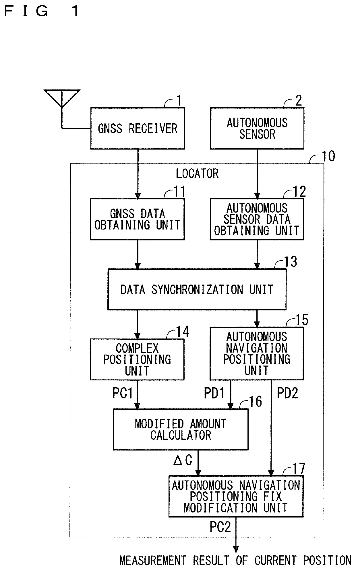
[0026]FIG. 1 illustrates a configuration of a positioning system according to Embodiment 1. As illustrated in FIG. 1, the positioning system includes a GNSS receiver 1, an autonomous sensor 2, and a locator 10. The assumption in Embodiment 1 is that the positioning system is loaded onto a vehicle. Hereinafter, the vehicle onto which the positioning system is loaded will be referred to as a “subject vehicle”. A part or the entirety of the positioning system need not be always loaded onto the subject vehicle, but may be, for example, constructed in a mobile device such as a mobile phone, a smartphone, or a portable navigation device. Although the configuration of the system shows the locator 10 externally equipped with the GNSS receiver 1 and the autonomous sensor 2, the locator 10 may include the GNSS receiver 1 and the autonomous sensor 2.

[0027]The GNSS receiver 1 receives a satellite signal transmitted from a GNSS satellite, decode the satellite signal to retrieve raw data, and out...

Example

Embodiment 2

[0066]In the locator 10 according to Embodiment 1, the accuracy of the time of the GNSS data is important because it influences the accuracy of the modified amount (ΔC) of autonomous navigation that is calculated by the modified amount calculator 16. Embodiment 2 proposes the GNSS receiver 1 that enables the locator 10 to accurately record the time of the GNSS data.

[0067]As described above, the GNSS receiver 1 performs a decoding process for retrieving the GNSS data (raw data) from the satellite signal, and a positioning process using the GNSS data (GNSS positioning). Since the GNSS data is large in amount and requires a certain time for the positioning process, there is a time lag since the GNSS receiver 1 receives the satellite signal and outputs the GNSS data until the locator 10 obtains the GNSS data.

[0068]According to Embodiment 2, the GNSS receiver 1 is configured to output a notification to the locator 10 at a time T1 of receiving the satellite signal and starting...

Example

Embodiment 3

[0074]FIG. 10 illustrates a configuration of an accuracy evaluation system for the locator 10 according to Embodiment 3. The configuration of the positioning system in FIG. 10 is obtained by further connecting a survey instrument 3, a reference data obtaining unit 18, and an accuracy evaluation unit 19 to the locator 10 in the configuration of FIG. 1. The locator 10 may include the reference data obtaining unit 18 and the accuracy evaluation unit 19.

[0075]The survey instrument 3 receives a satellite signal transmitted from a GNSS satellite, and performs positioning more accurately than the GNSS receiver 1, using the GNSS data (raw data) retrieved from the satellite signal. The positioning performed by the survey instrument 3 is not limited to the GNSS positioning. For example, when the survey instrument 3 includes an accurate autonomous sensor, the survey instrument 3 may perform the complex positioning using autonomous sensor data obtained by the autonomous sensor. Here...


PUM


Abstract

In a locator, a data synchronization unit calculates an interpolated value for autonomous sensor data which corresponds to a time of latest GNSS data. A complex positioning unit performs complex positioning using the latest GNSS data and the interpolated value for the autonomous sensor data. An autonomous navigation positioning unit performs first autonomous navigation positioning using the interpolated value for the autonomous sensor data, and performs second autonomous navigation positioning using latest autonomous sensor data. A modified amount calculator calculates a modified amount of autonomous navigation positioning, based on a difference between a result of the complex positioning and a result of the first autonomous navigation positioning. An autonomous navigation positioning fix modification unit modifies a result of the second autonomous navigation positioning using the modified amount to calculate a current position.

Description

TECHNICAL FIELD[0001]The present invention relates to a locator that measures a current position.BACKGROUND ART[0002]Known methods for measuring a current position include: Global Navigation Satellite System (GNSS) positioning that is positioning using data received from a GNSS satellite such as a Global Positioning System (GPS) satellite; autonomous navigation positioning that is positioning using data output from an autonomous sensor such as a speed sensor or an azimuth sensor; and complex positioning that is positioning using both of the data received from the GNSS satellite and the data output from the autonomous sensor.[0003]In the DESCRIPTION, data received by a GNSS receiver from a GNSS satellite (i.e., raw data) will be referred to as “GNSS data”, and data output by an autonomous sensor will be referred to as “autonomous sensor data”. Furthermore, the position obtained as a result of the GNSS positioning will be referred to as a “GNSS positioning fix”, the position calculate...

Claims


Application Information

Patent Timeline
IPC IPC(8): G01S19/48G01C21/28
CPCG01S19/48G01C21/28G01S19/49G01S19/47G01C21/165
Inventor KIDO, MASASHIISHIGAMI, TADATOMIFUJII, MASATOSHIFUJIMOTO, KOHEIKINOSHITA, RYUSUKE
Owner MITSUBISHI ELECTRIC CORP
Why Eureka
Try Eureka