Stationary measuring device for measuring or detecting a value at a utility installation

Pending Publication Date: 2022-06-09
KAMSTRUP
View PDF0 Cites 0 Cited by
  • Summary
  • Abstract
  • Description
  • Claims
  • Application Information

AI Technical Summary

Benefits of technology

The present patent aims to provide a consumption meter with more reliable and accurate current clock time information. This can be applied to various kinds of stationary measuring devices such as consumption meters, alarm sensors, acoustic noise detectors, chemical sensors, turbidity sensors, remotely controlled valves or other kinds of monitoring sensors. The patent proposes a method to determine a baseline for RTT (round-trip time) between sending a request and receiving the first clock time for each of a pre-determined number of consecutive requests. This baseline is used to filter out outliers of RTT and reduce the error in the first clock time. The baseline can be determined based on a sliding window or a weighted moving average (WMA).

Problems solved by technology

The frequency bands used in such a LPWAN are licensed, but have a relatively large link budget.
Thus, the “external” LPWAN can introduce high communication latencies that are unknown and unpredictable for the UP.
Such communication latencies may negatively affect the accuracy of an NTP response to a non-tolerable degree.
However, the cellular network time introduces a principle trust issue, because the base station as part of the LPWAN infrastructure is not controlled by the UP.
Also in this case, the second clock time, e.g. the cellular network time, cannot be trusted, because it deviates too much from the first clock time, e.g. the NTP time.
The latency issues are found to be worst for the first communicated data frames after establishing a LPWAN connection.

Method used


Image

  • Stationary measuring device for measuring or detecting a value at a utility installation
  • Stationary measuring device for measuring or detecting a value at a utility installation
  • Stationary measuring device for measuring or detecting a value at a utility installation

Examples


Embodiment Construction

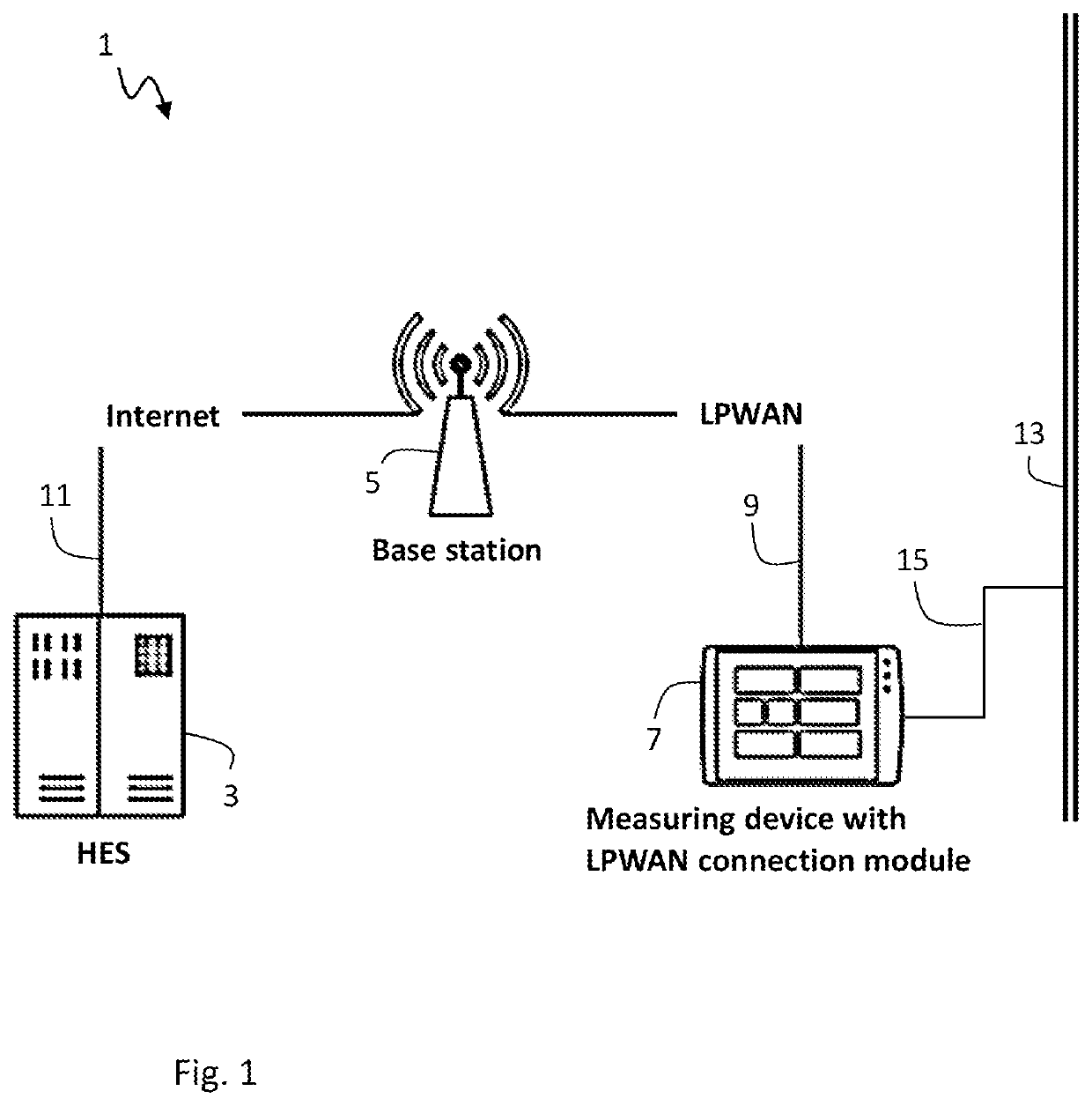
[0044]Referring to the drawings, FIG. 1 shows schematically a meter reading system 1 comprising a head-end system (HES) 3, a base station 5 of a Low Power Wide Area Network (LPWAN), and a measuring device 7 in form of a consumption meter. The measuring device 7 may be a electricity meter for registering a consumption of electric power at a utility installation, e.g. a private household, a public facility, or an industry facility. The measuring device 7 may alternatively be another kind of consumption meter, an alarm sensor or another kind of monitoring device that is supposed to send regularly information to the HES 3. The HES 3 receives and processes information from and / or controls the behavior of a multitude of measuring devices 7 that are installed in a multitude of utility installations.

[0045]The LPWAN is provided by a multitude of distributed base stations 5 of a public cellular mobile communications network. FIG. 1 shows only one of these base stations as the base station 5 t...


PUM


Abstract

A stationary measuring device (7) measures or detects a value at a utility installation. The measuring device includes a low power wide area network (LPWAN) communication module configured to establish a wireless communication connection to a LPWAN for communicating data to a head-end-system (HES) (3) via the LPWAN. The LPWAN communication module is configured to: send a request for a first clock time from the measuring device to a time server; receive the first clock time from the time server in response to the request; receive a second clock time from a base station of the LPWAN; compare the first clock time and the second clock time with each other; and determine a current clock time based on the second clock time if the second clock time lies within a pre-determined range about the first clock time.

Description

CROSS REFERENCE TO RELATED APPLICATIONS[0001]This application claims the benefit of priority under 35 U.S.C. § 119 of European Application 20212202.4, filed Dec. 7, 2020, the entire contents of which are incorporated herein by reference.TECHNICAL FIELD[0002]The present disclosure relates to a stationary measuring device for measuring or detecting a value at a utility installation, in particular to a consumption meter for registering a consumption of electric power, water, gas, or thermal energy.TECHNICAL BACKGROUND[0003]It is known that utility providers of electricity, water, gas and / or thermal energy use automatic meter reading (AMR) systems or advanced meter infrastructure (AMI) systems to efficiently and reliably manage customer billing. Such systems may be referred to as “dedicated” meter reading systems. Dedicated meter reading systems are characterized in that consumption meters are installed in a plurality of households, for instance, and communicate consumption data to a he...

Claims


Application Information

Patent Timeline
IPC IPC(8): H04W56/00H04J3/06H04L43/0864H04W24/10
CPCH04W56/0015H04J3/0638H04W84/12H04W24/10H04L43/0864H04W4/38H04J3/0667H04W56/001H04Q9/00H04Q2209/60
Inventor POULSEN, JONAS DRAMMESTRUPSTOBBE, KRISTIAN
Owner KAMSTRUP
Why Eureka
Try Eureka