System, apparatus and method for cancelling tonal interference in an orthogonal frequency division multiplexing (OFDM) receiver

a technology of orthogonal frequency division and receiver, applied in the direction of orthogonal multiplex, multiplex communication, transmission path division, etc., can solve the problems of loss of fidelity, different noise and interference sources, and possible tone interference, so as to remove tone interference

Active Publication Date: 2022-06-16
SILICON LAB INC
View PDF0 Cites 0 Cited by
  • Summary
  • Abstract
  • Description
  • Claims
  • Application Information

AI Technical Summary

Benefits of technology

[0003]In one aspect, an apparatus includes: a buffer to store orthogonal frequency division multiplexing (OFDM) samples of one or more OFDM symbols; a fast Fourier transform (FFT) engine coupled to the buffer, the FFT engine to receive the one or more OFDM samples from the buffer and convert each of the one or more OFDM samples into a plurality of frequency domain carriers; and a t

Problems solved by technology

In certain of these communication systems different noise and interference sources may be present.
In certain syste

Method used


Image

  • System, apparatus and method for cancelling tonal interference in an orthogonal frequency division multiplexing (OFDM) receiver
  • System, apparatus and method for cancelling tonal interference in an orthogonal frequency division multiplexing (OFDM) receiver
  • System, apparatus and method for cancelling tonal interference in an orthogonal frequency division multiplexing (OFDM) receiver

Examples


first embodiment

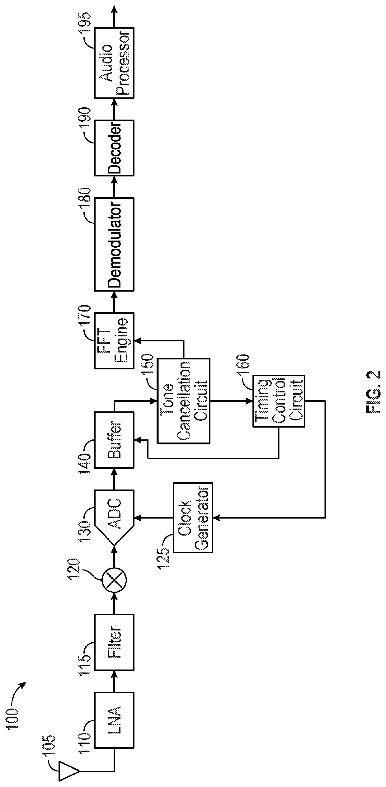
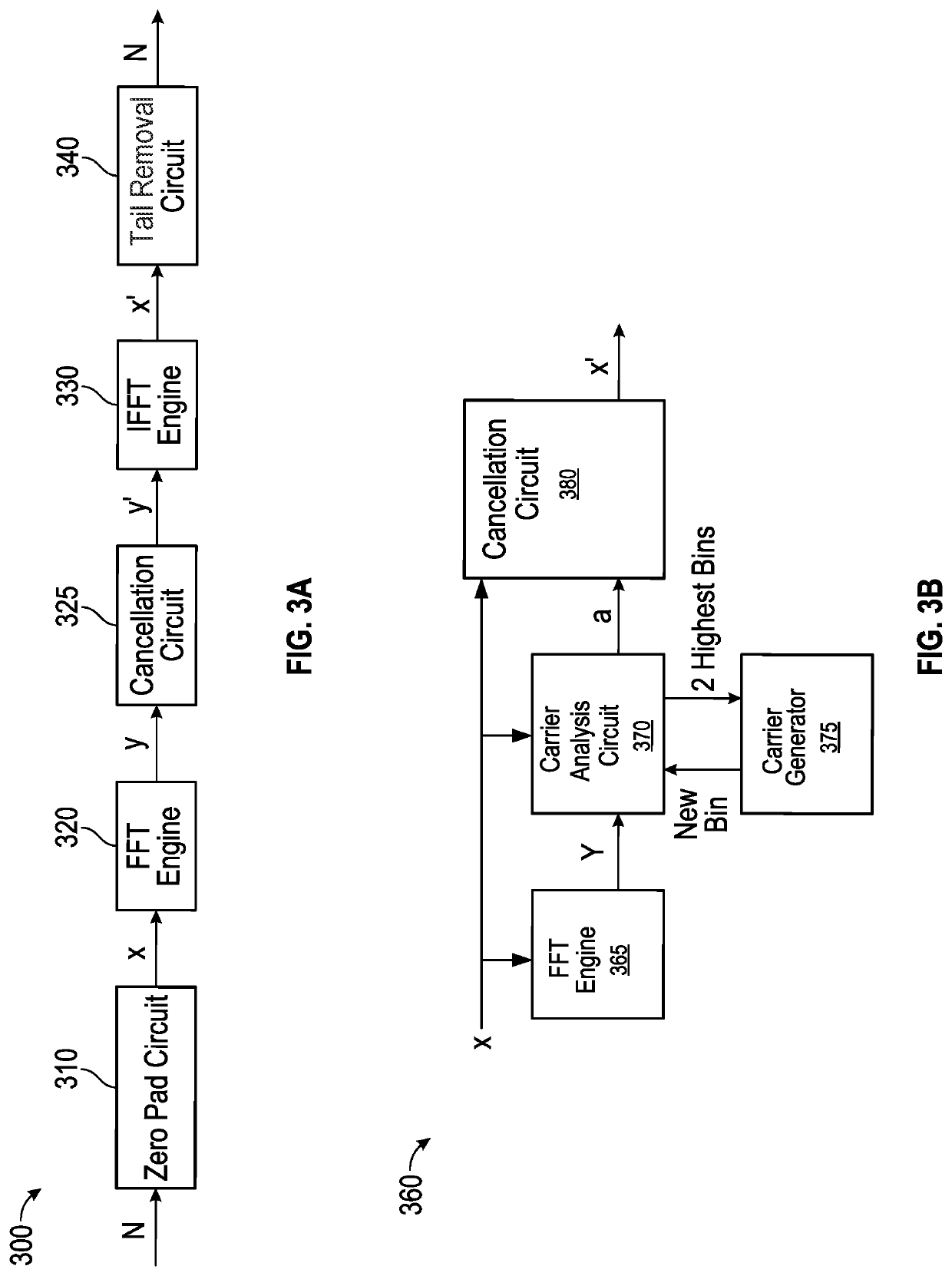
[0038]Referring to FIG. 3A, shown is a block diagram of a tone cancellation circuit in accordance with a In an embodiment, tone cancellation circuit 300 is one example implementation that may be incorporated in a receiver such as receiver 100 of FIG. 2 (more specifically as tone cancellation circuit 150).

[0039]As shown in FIG. 3A, tone cancellation circuit 300 includes a zero pad circuit 310. In an embodiment, pad circuit 310 receives an incoming time domain signal segment of length N and passes it with some additional number of zeros to increase an oversampling factor. In an implementation in which it is desired to increase resolution by a factor of M for a signal segment of length N, zero pad circuit 310 may add (M−1)N zeros. As such, zero pad circuit 310 provides a time domain signal x that is zero padded and provided to an FFT engine 320, which may transform this time domain signal into the frequency domain as a frequency spectrum having M×N samples (y(n)).

[0040]Still with refe...

second embodiment

[0044]In another embodiment, a tone cancellation circuit may take the form shown in FIG. 3B. Illustrated in FIG. 3B is a block diagram of a tone cancellation circuit in accordance with a In an embodiment, tone cancellation circuit 360 is another example implementation that may be incorporated in a receiver such as receiver 100 of FIG. 2 (more specifically as tone cancellation circuit 150).

[0045]As shown, an incoming time domain signal X is provided to an FFT engine 365, which may transform this time domain signal into the frequency domain as a frequency spectrum Y. In turn, the frequency carriers are provided to a carrier analysis circuit 370. In embodiments herein, carrier analysis circuit 370 may be configured to identify the highest magnitude bins within the frequency carriers. In an embodiment, carrier analysis circuit 370 may identify a highest magnitude frequency bin and its two neighboring bins. In turn, from these 3 frequency bins the two highest bins are identified and pro...


PUM


Abstract

In one aspect, an apparatus includes: a fast Fourier transform (FFT) engine to receive orthogonal frequency division multiplexing (OFDM) samples of one or more OFDM symbols and convert the one or more OFDM samples into a plurality of frequency domain carriers; and a tone cancellation circuit coupled to the FFT engine to receive the one or more OFDM samples and generate a plurality of frequency carriers for the one or more OFDM samples, identify a highest magnitude frequency carrier of the plurality of frequency carriers, and remove tone interference from the OFDM samples based at least in part on the highest magnitude frequency carrier.

Description

BACKGROUND[0001]Radio receivers are omnipresent in modern technology. In addition to standalone radios for receipt of broadcast radio signals, all manners of tech and non-tech devices include some type of radio receiver (and often paired with a transmitter). Such modem circuitry is present in any device having wireless capabilities. While some broadcast radio signals are transmitted with analog coding (e.g., conventional AM and FM signals), other terrestrial and satellite wireless communication systems use some type of digital encoding. Some example digital radio systems include National Radio System Committee (NRSC-5C, also known as HD™ radio), Digital Audio Broadcasting (DAB), Digital Radio Mondiale (DRM) or other standard.[0002]In certain of these communication systems different noise and interference sources may be present. In certain systems, a tone interference may exist as a result of co-channel interference. While in the time domain such interference may not be especially gr...

Claims


Application Information

Patent Timeline
IPC IPC(8): H04B1/12H04B1/16H04L27/26H04B1/10H04L5/00
CPCH04B1/12H04B1/16H04L5/001H04B1/1027H04L27/26524H04L27/265H04J11/0066
Inventor KLEINERMAN, ALEXANDER
Owner SILICON LAB INC
Why Eureka
Try Eureka