Camera module and method for manufacturing a camera module

US20220191354A1Pending Publication Date: 2022-06-16ROBERT BOSCH GMBH

Image

  • Camera module and method for manufacturing a camera module
  • Camera module and method for manufacturing a camera module

Examples


Embodiment Construction

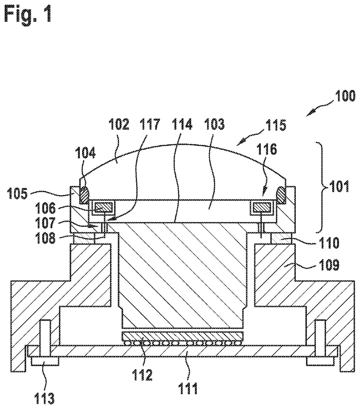
[0034]FIG. 1 shows camera module 100 by way of example. This module includes a circuit board 111, on which image sensor 112 is situated. Circuit board 111 is connected here in the example with the aid of connecting elements 113 to an objective holder 109.

[0035]Connecting elements 113 are designed here by way of example as screws. Objective holder 109 is designed to hold objective 115. Objective holder 109 may be made of metal or plastic. Objective 115 includes lens housing 105 and multiple optical lenses situated inside lens housing 105. Lens housing 105 may be made of metal or plastic. In the example shown here, objective 115 includes front lens 102, a second optical lens 103 situated at front lens 102, and further optical lenses 114. As shown in the example here, a seal element 104 may be situated between lens housing 105 and front lens 102. Furthermore, camera module 100 includes a temperature control element 106. Temperature control element 106 is designed to influence the tempe...


PUM


Abstract

A camera module. The camera module includes a circuit board on which at least one image sensor is situated; an objective including a lens housing and multiple optical lenses situated inside the lens housing; an objective holder, which is connected to the circuit board and is designed to hold the objective; and at least one temperature control element, which is designed to influence the temperature of at least one front lens of the objective; a second optical lens being situated at the front lens. The front lens and / or the second optical lens includes / include at least one recess, the at least one temperature control element being situated in the at least one recess.

Description

CROSS REFERENCE[0001]The present application claims the benefit under 35 U.S.C. Β§119 of German Patent Application No. DE 102020215734.0 filed on Dec. 11, 2020, which is expressly incorporated herein by reference in its entirety.FIELD[0002]The present invention relates to a camera module for a motor vehicle and a method for manufacturing a camera module.BACKGROUND INFORMATION[0003]Camera modules are usable in industrial, safety-relevant applications and in consumer products. In the automotive field, for example, a camera module has to be designed in such a way that it functions both in very cold (approximately βˆ’40Β° C.) and very hot (approximately +105Β° C.) surroundings. Electronic components of camera modules usually include a power loss during operation, due to which self-heating occurs. For this reason, the camera modules are usually designed in such a way that good heat dissipation to the surroundings may take place. Nonetheless, it may be necessary, regardless of the temperature ...

Claims


Application Information

Patent Timeline
16 Jun 2022
Publication
US20220191354A1
IPC
H04N5/225; G03B17/12
CPC
H04N5/2252; H04N5/2257; G03B17/12; H04N23/54; H04N23/55; G03B17/55; G03B30/00; H04N23/52
Inventors
MOEHRLE, ANDREAS; FINNAH, GUIDO BERND