
Substrate heat treatment apparatus

a heat treatment apparatus and substrate technology, applied in the field of substrate heat treatment apparatus, can solve the problems of difficult temperature control, overshooting of target temperature in the cover, etc., and achieve the effect of stabilizing temperature control and reducing time taken

Inactive Publication Date: 2008-12-23
DAINIPPON SCREEN MTG CO LTD
View PDF3 Cites 11 Cited by
  • Summary
  • Abstract
  • Description
  • Claims
  • Application Information

AI Technical Summary

Benefits of technology

[0008]This invention has been made having regard to the state of the art noted above, and its object is to provide a substrate heat treatment apparatus capable of stabilizing temperature control near a target temperature by adjusting a distance of a cover during a temperature control process, while reducing the time taken in a temperature increasing process.
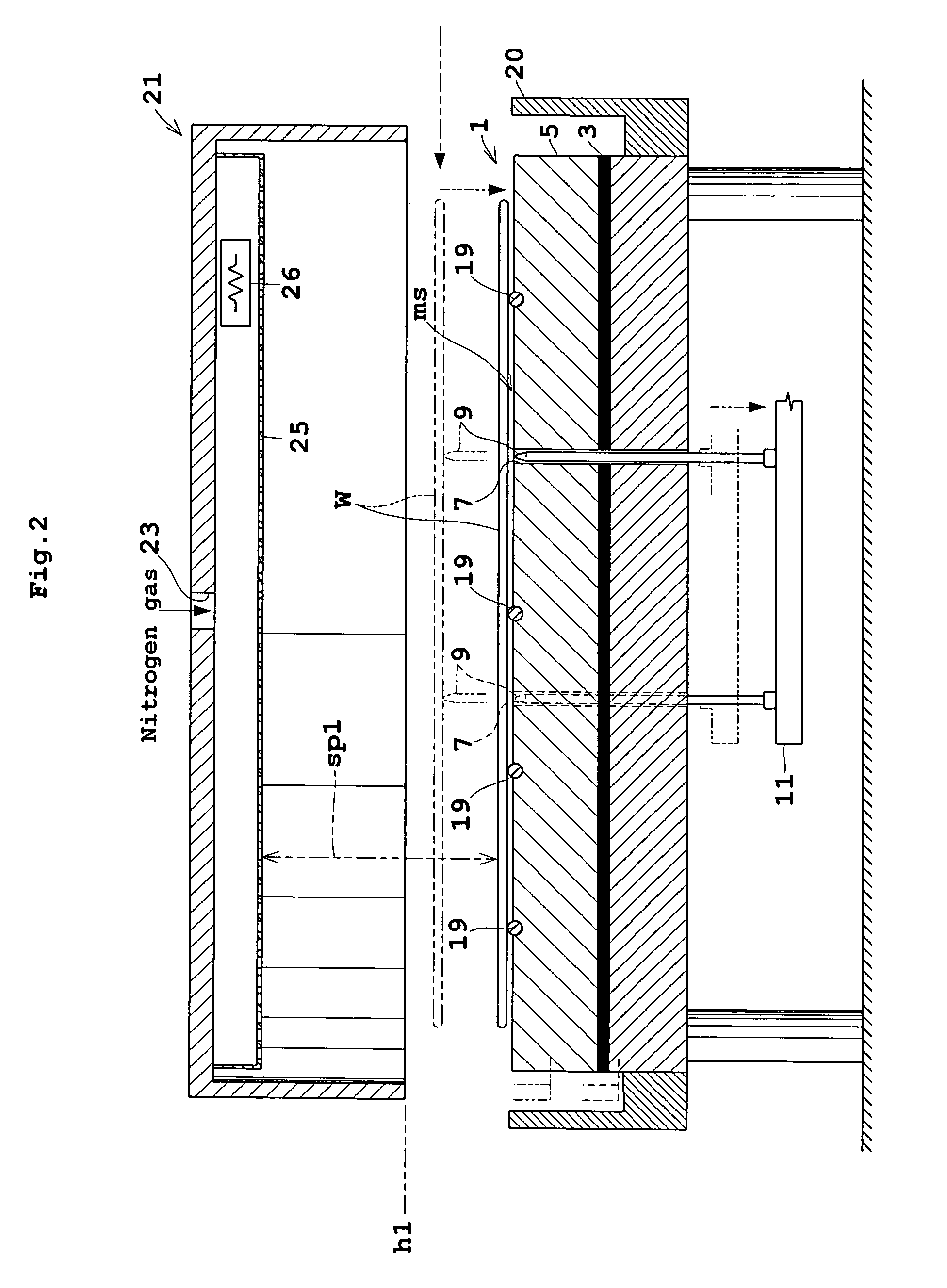
[0010]According to this invention, the control device causes the adjusting device to adjust the space between the cover and bake plate to the transport space, transitional space and steady space in the stated order. That is, the transport space is set for loading the substrate, and the transitional space is set for a temperature increasing process to increase temperature at a rapid rate. Subsequently, the steady space is set, thereby preventing an interaction between temperature controls of the cover and bake plate. As a result, the temperature increasing process is reduced in time, and temperature control is stabilized near a target temperature.
[0014]A space of 5 to 20 mm can prevent heat interference between the bake plate and cover.

Problems solved by technology

However, the cover and bake plate are subjected to separate temperature controls, and mutual heat interference would render the temperature controls difficult.
The strong heating action of the bake plate can cause the temperature in the cover to overshoot the target temperature.

Method used


Image

  • Substrate heat treatment apparatus
  • Substrate heat treatment apparatus
  • Substrate heat treatment apparatus

Examples


Embodiment Construction

[0025]An embodiment of this invention will be described hereinafter with reference to the drawings.

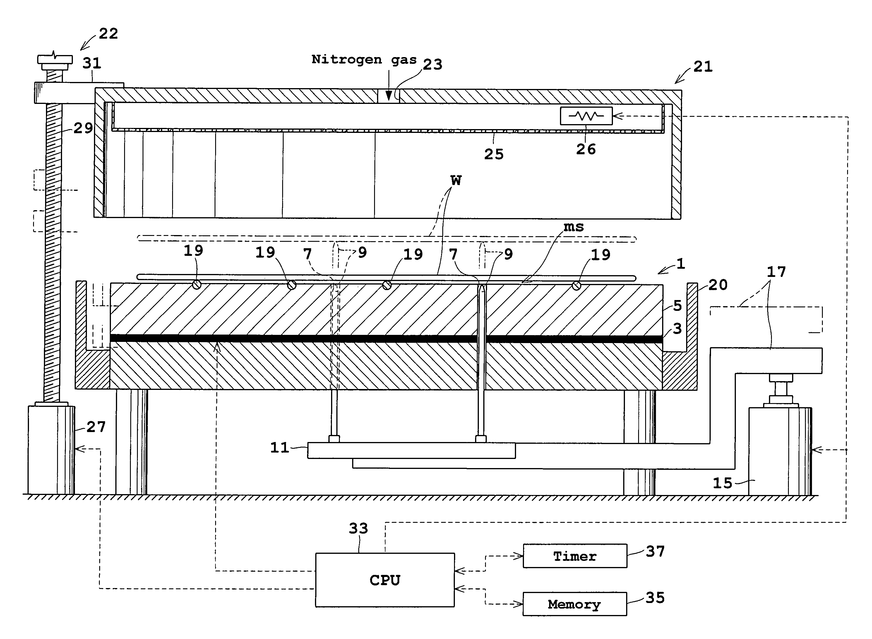
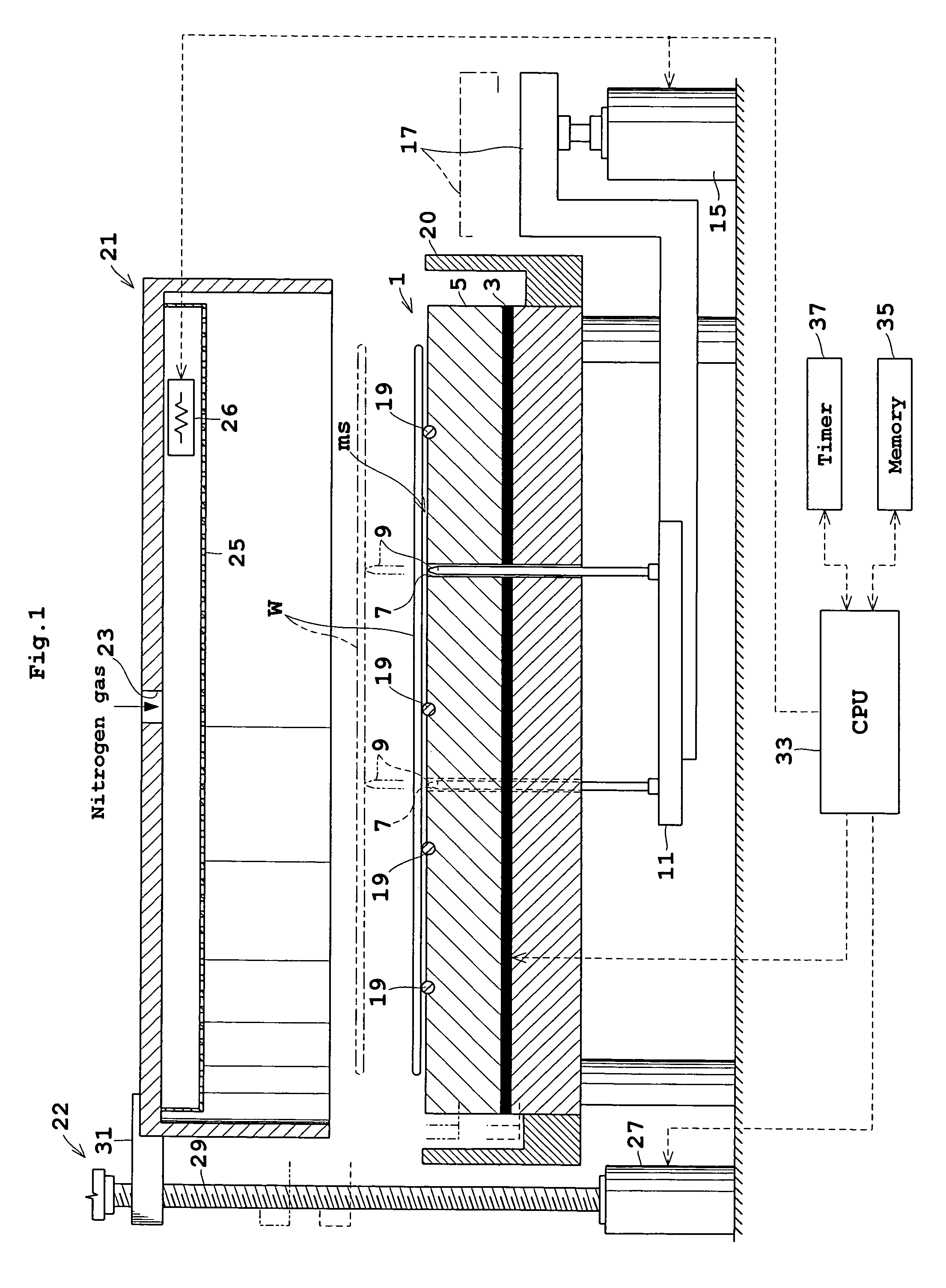
[0026]FIG. 1 is a view showing an outline of a substrate heat treatment apparatus according to this invention.

[0027]A bake plate 1 for supporting a substrate or wafer W on an upper surface thereof has a heating element 3 such as a mica heater mounted in a lower portion thereof. A heat transfer portion 5 between the heating element 3 and the upper surface of bake plate 1 has a plurality of heat pipes, not shown, embedded therein. Cooling grooves, not shown, are formed between the heat pipes for circulating a cooling fluid.

[0028]Instead of the heat transfer portion 5 having a plurality of heat pipes embedded therein, the heat transfer portion 5 itself may have a heat pipe structure.

[0029]The bake plate 1 has three perforations 7 extending from the upper surface to the lower surface. These perforations 7 are formed in positions corresponding to the apexes of an equilateral triangle in pla...


PUM

PropertyMeasurementUnit
sizeaaaaaaaaaa
temperatureaaaaaaaaaa
timeaaaaaaaaaa

Abstract

A substrate heat treatment apparatus for heat-treating a substrate includes a bake plate for supporting the substrate, and a cover disposed above the bake plate and temperature-controlled for securing a heat-treating atmosphere of the bake plate. An adjusting device adjusts a space between the cover and the bake plate. A control device adjusts the space, through the adjusting device, successively to a transport space for allowing transport of the substrate, a transitional space smaller than the transport space and close to the bake plate, and a steady space smaller than the transport space and larger than the transitional space.

Description

BACKGROUND OF THE INVENTION[0001](1) Field of the Invention[0002]This invention relates to a substrate heat treatment apparatus for heat-treating substrates such as semiconductor wafers and glass substrates for liquid crystal displays (hereinafter simply called substrates).[0003](2) Description of the Related Art[0004]A conventional substrate heat treatment apparatus of the type noted above has a bake plate for supporting a substrate, and a cover for securing a heat-treating atmosphere above the bake plate. The cover has a heater. By controlling the temperature of the cover, a target temperature is attained in a short time even when a preset temperature is changed (as disclosed in Japanese Unexamined Patent Publications Nos. 1997-8049 and 1998-189429, for example).[0005]A different apparatus has a construction for adjusting varied locations on a surface of a substrate placed on a bake plate relative to a cover, to adjust a temperature distribution over the surface of the substrate (...

Claims


Application Information

Patent Timeline
Patent Type & Authority Patents(United States)
IPC IPC(8): G03D5/00G03F7/00H05B3/68
CPCH01L21/67109H01L21/68742H01L21/6875H01L21/68778
Inventor KAMEI, KENJI
Owner DAINIPPON SCREEN MTG CO LTD
Learn More